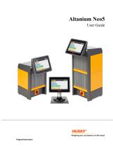
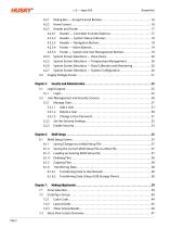
General Information: The Altanium Neo5 User Guide provides essential information for the safe operation and maintenance of the Altanium Neo5 system. Husky Injection Molding Systems Limited reserves the right to make product changes to enhance features and performance, which may include new safety measures communicated through bulletins. Customers are permitted to reproduce the document for internal use only.
Support and Services: For on-site service, contact the nearest Husky Regional Service and Sales office. Non-emergency inquiries can be directed to
[email protected]. Product upgrades are available to improve output and functionality, and spare parts can be ordered online or through Husky Parts Distribution Centers.
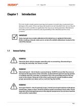
Chapter 1: Introduction- General Safety: Emphasizes the importance of adhering to safety signs and guidelines.
- Purpose and Restrictions: Details the intended use of the equipment and any restrictions.
- Specifications: Includes input wiring, environmental operating conditions, equipment ratings, and dimensions.
- Lifting Instructions: Provides guidelines for safely lifting the controller and related components.
Chapter 2: Hot Runner Temperature Control- Temperature Control Types: Describes open loop control and zone configuration for zero cross and phase angle control.
- Heater and Thermocouple Information: Guidance on determining heater size and understanding thermocouple types and color codes.
Chapter 3: System Connection- Startup Procedures: Checklist for connecting the system to the mold and power source.
Chapter 4: Operator Interface- Interface Overview: Details screens, buttons, and navigation for system operation.
- System Screen Selections: Includes zone views, temperature management, data collection, and system configuration.
Chapter 5: Security and Administration- User Management: Instructions for login/logout, managing users, and setting security parameters.
Chapter 6: Mold Setups- Mold Setup Management: Procedures for saving, loading, deleting, and transferring mold setup files.
Chapter 7: Making Adjustments- Zone and Group Management: Instructions for selecting zones, creating groups, and adjusting settings.
- Advanced Settings: Includes manual and remote standby/boost, heater types, and control settings.
Chapter 8: Mold Diagnostics- Test Settings: Provides guidelines for conducting diagnostic tests on the mold.
Overview: This document is a user guide for the Altanium Neo5, a hot runner temperature control system. It provides detailed instructions on installation, operation, and maintenance to ensure optimal performance.
Installation and Setup: The guide outlines the steps for safely lifting and moving the Neo5 using straps and a lifting device. It emphasizes the importance of avoiding damage to cables and the device's finish. The setup includes connecting power and thermocouple cables, ensuring proper grounding, and verifying system connections before startup.
Temperature Control: The Neo5 supports both open and closed loop temperature control. Open loop control is used without thermocouple feedback, while closed loop control uses internal or external thermocouples for precise temperature management. The system can configure zones using Zero Cross Control or Phase Angle Control to adjust power delivery to heaters.
Heater Configuration: The guide explains the importance of selecting the correct heater size and provides instructions for determining heater resistance and wattage using Ohm's Law. It warns against undersized heating elements, which can lead to performance issues.
Thermocouple Types: The Neo5 uses ANSI color codes for thermocouples, with a reference table provided for different international standards.
System Connection: Before startup, users must ensure the system is clean, properly connected, and free from obstructions. The guide includes a checklist for connecting the system to the power source and starting up safely.
Operator Interface: The Neo5 features a touch-sensitive display for system navigation and operation. The interface includes various screens for zone views, temperature management, data collection, and system configuration. It also provides buttons for system control and status indicators.
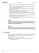
Safety Warnings: The document contains multiple warnings about electrical hazards, emphasizing the need to disconnect power before performing tests or maintenance. It also highlights mechanical hazards associated with the touch screen and advises using fingers only to operate it.
System Modes: The guide describes different system modes, including Stop, Running, Manual Standby, Remote Standby, Manual Boost, and Remote Boost, each with specific operational behaviors.
System Modes and Processes: The document outlines various system modes and processes for the Altanium Neo5, including Active Reasoning Technology (ART) for tuning, thermocouple calibration, mold diagnostics, firmware updates, and multiple bake-out cycles to remove moisture from molds. The system also features a soft start process for gradual heating and various stages for heating and cooling zones.
Security and User Management: Chapter 5 details user management functions, including login/logout procedures and role-based access control. Users can be assigned roles such as Operator, Supervisor, or Administrator, each with specific access rights. The administrator can manage users, change passwords, and configure security settings to control access to system features.
Mold Setup Management: Chapter 6 describes the mold setup process, which involves managing files related to mold setups, images, and documents. Users can load, save, copy, delete, and transfer mold setup files using USB or network connections. The system allows for the creation of new mold setups and the modification of existing ones.
Adjustments and Zone Management: Chapter 7 explains how to adjust process settings for mold setups, including selecting and grouping zones for easier management. Users can create up to 10 groups, assign names, and color-code them for better visualization. The Neo2 View provides a graphical representation of zone status, facilitating quick assessments of mold conditions.
Overview: The document is a user guide for the Altanium Neo5 system, focusing on temperature and power management across multiple heating zones. It provides detailed instructions on how to monitor and adjust settings for optimal performance.
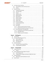
Temperature Bar: Each zone's temperature is displayed with a color-coded bar. Green indicates the molding window, white is the setpoint, and an arrow shows the actual temperature. Yellow arrows indicate temperatures outside the graph range, while black arrows are within range. Alarm and abort windows are marked in yellow, red, and blue, respectively.
Text View Screen: This screen presents zone information in a table format, offering a comprehensive view of the process. Users can navigate to the Quick Set screen by selecting a zone row. Columns include zone number, name, setpoint, actual temperature, power output, and more.
Quick Set Screen: Allows users to change zone settings. Users can adjust temperature setpoints, power levels, and regulation modes (Auto, Manual, Monitor). Alarm and abort windows can also be configured here.
Setpoint Limits: Users can define minimum and maximum limits for temperature and power setpoints to ensure safe operation.
Manual Standby and Boost: These features allow users to temporarily lower or increase zone temperatures and power levels. Standby and boost modes can be activated manually or remotely, with configurable duration timers.
Remote Standby and Boost: Activated via digital input, these modes adjust zone settings based on remote signals. Users can set temperature and power ranges, as well as delay and duration timers for these modes.
Operational Descriptions: Detailed explanations of how standby and boost modes operate, including timer settings and input modes, are provided to ensure users understand system behavior.
Trigger System Operations: The document outlines various operational modes for the Trigger System, including immediate entry into Boost mode, delayed entry, and indefinite Boost mode. The system can be controlled via Start or Stop buttons in Trigger or ON/OFF modes. Specific conditions for entering and exiting Boost mode are detailed, such as timer expiration and input signal activity.
Heater Types Configuration: Users can assign names to custom heater types and select zones for specific heater types. The process involves using a keyboard interface to enter names and selecting from a dropdown list to assign heater types to zones.
Advanced Settings: Settings include output power limits, zone slaving, sensor input configuration, and output mode selection. The document explains how to configure these settings to ensure proper operation and response to thermocouple failures.
Control Settings and ART: The document describes the Active Reasoning Technology (ART) and its role in automatic control. Users can switch from ART to PID control if necessary, with specific parameters for Proportional, Integral, and Derivative values. ART settings include reset, re-ART, and cancel functions.
Zone Slave Functionality: In case of thermocouple failure, zones can be slaved to other zones to maintain operation. The document details both automatic and manual slaving processes, including the use of the Automatic Manual Control (AMC) function if automatic slaving is not possible.
Mold Diagnostics: Diagnostics are used for troubleshooting and verifying mold wiring integrity. The document provides steps for setting test parameters, running diagnostics, and ensuring safety during testing. It emphasizes the importance of proper grounding and connection verification before testing.
Typical PID Values and Oscillation Causes: The document lists typical PID values for different types of heaters and probes, and identifies common causes of oscillation in control terms, such as incorrect proportional, integral, or derivative settings.
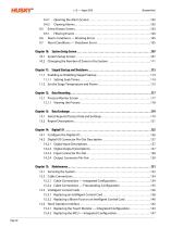
Specifications and Procedures: The document provides detailed instructions for testing and configuring the Altanium Neo5 system, focusing on mold testing and heater circuit management. Key procedures include selecting zones for testing, ensuring the Neo5 system is stopped before running tests, and understanding the importance of zone cooling time and maximum test time to prevent damage to heaters.
Zone Cooling Time: It is crucial to wait for a specified cooling time between tests to ensure accurate results, especially for large manifolds. The default cooling time is set to 10 seconds, but this can be adjusted per mold setup.
Maximum Test Time: To prevent damage to heaters, the maximum test time can be set for each zone, with a default of 2 minutes. This is particularly important for configurations that may not support peak temperatures.
Test Definitions: The document outlines various tests such as the Test Heaters Test, Test Sensor Test, and Test Wiring Test, each designed to ensure the proper functioning of the system components.
Mold Test Results: The results screen provides detailed feedback on each zone, including sensor status, fuse condition, thermocouple functionality, and wiring correctness. It also includes tests for ground faults and moisture in heaters.
Automatic Thermocouple Wiring: The Neo5 system can automatically rewire thermocouples to correct zones if errors are detected, enhancing the accuracy of the mold setup.
Earth Leakage and Bake Out System: The system continuously monitors for earth leakage and can perform a bake out to remove moisture from heaters. Users can configure the earth leakage limit and bake out cycles to suit their needs.
Soft Start Routine: This routine ensures even thermal expansion by warming all zones simultaneously. The soft start limit can be adjusted to maintain thermal uniformity.
Alarm and Event History: The system includes an alarm screen to display errors and an event history screen to track past alarms and system changes. Users can filter events to view specific occurrences.
Alarm and Abort Conditions: Alarm conditions trigger warnings without shutting down the system, while abort conditions result in system shutdowns to prevent damage.
Warning Errors: Warning errors include conditions like 'Alarm Over Temp' and 'Alarm Under Temp', where a zone's temperature exceeds or drops below its setpoint by a specified limit. 'Auto Slave Enabled' and 'AMC Active' occur when a thermocouple becomes defective, with the system either slaving the zone to another or switching to manual control. 'Power Deviation' and 'No Heater' indicate deviations in power output or heater failures.
Shutdown Errors: Shutdown errors trigger system shutdowns and include 'Abort Over Temp' and 'Abort Under Temp', where temperatures exceed abort limits. 'Configuration' errors occur when control parameters differ from expected values. 'Circuit Overload', 'Control Card Over Temperature', and 'Earth Leakage' are hardware-related errors. 'Lost Thermocouple', 'Maximum Temp Limit', and 'No Response' indicate issues with temperature sensing and response. 'Over Current Limit', 'Receive Data Comm', and 'Rev. Thermocouple' involve current and communication errors.
System Setup Screen: The System Setup screen allows configuration of system-wide preferences, including serial number, model, software version, and various control parameters like 'Auto Save Mold Setup', 'Force Phase Angle Control', and 'Global Output Power Limit'. It also includes settings for alarm sensitivity, temperature limits, and soft start processes.
Staged Startup and Shutdown: This feature allows heating or cooling zones in a predetermined order using stages. Each stage can have a separate setpoint and soak timer. The process prevents issues like misalignment and leaking by ensuring proper heating and cooling sequences.
Data Recording: Data recording tracks mold operation to optimize processes and track errors. The Process Monitor screen displays graphs of parameters over time, allowing analysis of system behavior during errors.
Data Exchange: Reports and images can be stored on the Neo5 hard drive and transferred to a network or USB device for sharing or printing.
Data Exchange and Report Saving: The document outlines the process for saving reports and process data using the Altanium Neo5 system. Users can select reports to save via the Data Exchange screen, choosing between saving to a USB device, the Neo5 hard drive, or a network location. The system allows for setting time intervals for data saving and selecting specific process variables.
Report Descriptions: Various types of reports can be generated and saved, including Zone Information (brief and detailed), Diagnostics, Mold Setup, Zone Calibration, Power Deviation Data, and Event Data. Each report type includes specific data points such as zone numbers, setpoints, temperatures, power, and event details.
Digital I/O Configuration: The Neo5 system includes four inputs and outputs, configurable via the Digital I/O section. Inputs include Remote Standby, Boost, Start, and Stop, while outputs include Alarm, Abort, At Temperature, and Run Light. The document provides detailed pin-out descriptions for connecting these inputs and outputs.
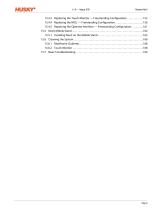
Maintenance Procedures: Maintenance tasks for the Neo5 include checking cable connections, replacing control cards, and fuses. The document emphasizes safety precautions, such as locking out power before servicing and handling electrostatic-sensitive components with care.
Intelligent Control Cards: The Neo5 uses X-Series and H-Series Intelligent Control Cards, which are not interchangeable. The document provides instructions for replacing these cards and their fuses, highlighting the importance of using the correct type and rating of fuses to avoid system issues.
Specifications and Safety Warnings: The document outlines the procedures for handling and replacing components of the Altanium Neo5 system, emphasizing the importance of safety precautions. It warns of electrical and mechanical hazards, advising to turn off all power and follow Lock Out Tag Out procedures. Electrostatic discharge precautions are also highlighted, recommending the use of a ground strap when handling sensitive cards.
Neo5 Operator Interface: The Neo5 operator interface is used for entering and displaying molding parameters. It consists of a touch monitor and a master control unit (MCU), available in integrated and standalone configurations. The interface should only be serviced by replacing the touch monitor or MCU as complete subassemblies.
Replacing Components: Detailed procedures are provided for replacing the touch monitor and MCU in both integrated and freestanding configurations. Key steps include rotating the monitor, unplugging connectors, loosening fasteners, and carefully removing and installing components. Important safety warnings are reiterated throughout these procedures.
Neo5 Mobile Stand: The Neo5 can be mounted on a mobile stand, available in two variants: C6-1 (tall) and C6-2 (short). The stand allows for optimal viewing height and mobility. Assembly instructions emphasize the importance of using the correct stand and controller combination to prevent tipping.
Cleaning Instructions: Cleaning guidelines for the mainframe and touch monitor are provided, recommending the use of non-abrasive, non-ammonia, and non-alcohol based cleaners. Caution is advised to avoid spraying liquids directly onto surfaces to prevent damage.
Troubleshooting: The document includes troubleshooting procedures for common issues such as read time out, blown fuses, temperature irregularities, ground faults, and no response from heaters. Solutions involve checking connections, inspecting cables, and ensuring proper setup and voltage supply.
Conclusion: The document provides comprehensive instructions for maintaining and servicing the Altanium Neo5 system, with a strong emphasis on safety and proper handling techniques to prevent damage and ensure efficient operation.
Troubleshooting Procedures for Altanium Neo5:
Voltage and Current Issues: Ensure the mold operates at the correct voltage. If not, connect to a sufficient voltage supply. Use current readings to check heater functionality. No current may indicate wiring faults or a defective heater.
Thermocouple Problems: Issues such as shorted, detached, mis-positioned, or pinched thermocouples can occur. Verify proper routing and termination of thermocouples. Reversed polarity or non-calibrated cards can also cause issues.
Temperature Reading Errors: If the temperature is far beyond 1100°F (600°C) or shows 32°F (0°C), check for broken circuits or bad thermocouples. Shorting the thermocouple input should display ambient temperature; if not, recalibrate or replace the card.
Screen and Communication Issues: No screen display may result from a bad touch monitor or computer. Check for missing phases in the power supply. Replace faulty components with known good units to restore functionality.


 Schöttli® Medical Molds
 UltraSync-E Technology
 UNIFY™
 Shotscope NX
 H-PET AE System
 ultra helix valve gate
 Pro-Act Program
 PowerPro G
 Altanium Servo Control
 Ultra SideGate
 Ultra Helix TM Valve Gate
 Ultra 350 Nozzles
 Ultra 1000 Nozzles
 Ultra 250 Nozzles
 Express conversion Programs
 Encore program
 Ultra SideGate
 UNIFY
UNIFY Top Entry Robots
 Specialty Closures
 ShotscopeNX
 PRONTO Hot Runners
 ProAct Program
 Machine Audits
 HyPET Recycled Flake
 HyPET Preform Systems
 Ultra Valve Gate Technology
 H-MED AE
 Altanium Neo2


 Hylectric Machines
 HyCAP Beverage Closures
 Thinwall Packaging
 Company Overview
 Altanium Delta3

