- Catalogs
- Husco International
- 5000-valve
5000-valve
1 /36Pages

5000-valve
1 /36Pages
Catalog excerpts
Control focused MODEL 5000 Sectional valve technology driven
Open the catalog to page 1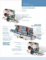
Model 5000 Section al Cu taway Inlet/Outlet SECTION CUTAWAY Top Inlet Port Top Outlet Port Optional End Inlet Port Auxiliary Valve Port Accepts 5060 Style Main Relief Optional End Outlet Port PARALLEL CIRCUIT SPOOL SECTION CUTAWAY “A” Work Port Auxiliary Port – See Work Port Feeder Core or “Bridge” Pages 20-22 for Work Port Options Parallel Passage Load Check Spring Centered End Mechanism–Many Other Options Available O-Ring/Wiper Spool Seal Combination Thru Neutral Passage Low Pressure or Tank Passage Precision Spool with Metering Notches Patented One O-Ring Seal Between Sections – an Industry...
Open the catalog to page 2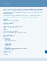
Since 1946, HUSCO International has established itself as the resource OEM engineers rely on for help designing high quality, innovative, customized products that meet precision motion control requirements. This catalog fully illustrates the component features and options you need to specify, build and service a Model 5000 sectional body directional control valve. Designed for hydraulic systems, the Model 5000 valve line is made from an assortment of valve component sections and options that deliver the desired control valve circuit to match your specific application. FEATURES • 3000 psi operating...
Open the catalog to page 3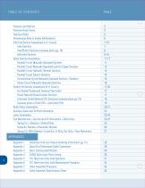
Pressure Drop Curves 5 Dimensional Data in Inches (Millimeters) 6 Inlet End Section Assemblies (L.H. Covers) 7-10 Inlet/Outlet Sections (cutaway photo pg. 19) 8 Spool Section Assemblies 11-17 Parallel Circuit Manually Operated Sections 11 Parallel Circuit Manually Operated Lock-Out Spool Sections 12 Parallel Circuit Hydraulic Remote Sections 13 Parallel Circuit Electric Sections 14 Conventional Circuit Manually Operated Sections (Tandem) 15 Series Circuit Manually Operated Sections 16 Outlet End Section Assemblies (R.H. Covers) 17-20 End Outlet/Turnaround Sections/Top Outlet 17 Power Beyond/Closed-Center...
Open the catalog to page 4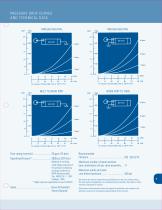
PRESSURE DROP CURVES THROUGH NEUTRAL THROUGH NEUTRAL INLET TO WORK PORT WORK PORT TO TANK rated fatigue pressure of NFPA Recommended * Higher pressure applications consult HUSCO Buna-N Standard Vitron Optional Maximum number of spool sections Maximum outlet port/tank We reserve the right to amend these specifications at any time without notice. The only warranty applicable is our standard written warranty. We make no other warranty, expressed or implied. Performance characteristics shown are typical of production units tested in the laboratory and are not necessarily representative of any one...
Open the catalog to page 5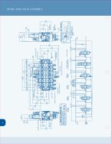
Mode l 5 0 0 0 Valv e A sse mbly
Open the catalog to page 6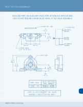
NLET SECTION ASSEMBLIES WITH END PORT. NO AUXILIARY VALVE PORT OPTION (FOR APPLICATIONS THAT DO NOT REQUIRE A MAIN RELIEF VALVE AT THE VALVE ASSEMBLY) USED IN SECTION©OF THE VALVE ASSEMBLY SPECIFICATION SHEET
Open the catalog to page 7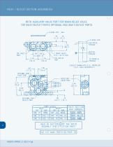
WITH AUXILIARY VALVE PORT FOR MAIN RELIEF VALVE. TOP INLET/OUTLET PORTS OPTIONAL END INLET/OUTLET PORTS -•—O-RING SIDE ■LOW PRESS. USED IN SECTION (T) OF THE VALVE ASSEMBLY SPECIFICATION SHEET SEE CUT-AWAY PHOTO ON PAGE 19
Open the catalog to page 8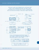
MID-INLET COMBINER SECTION ASSEMBLY MID-INLET PUMP FLOW COMBINES WITH UPSTREAM PUMP FLOW TO FEED DOWNSTREAM SPOOL SECTIONS. WHEN UPSTREAM SPOOL SECTIONS ARE ACTIVATED. DOWNSTREAM SPOOL SECTIONS ARE EXPOSED TO MID-INLET PUMP FLOW ONLY. INLET PORT OUTLET PORT O-RING SIDE CIRCUIT SHOWN WITH R.V. INSTALLED AUXILIARY VALVE PORT CONTROLS DOWNSTREAM VALVE SECTIONS ONLY. MID-INLET SECTIONS ARE USED IN-BETWEEN SPOOL SECTIONS EITHER TO ADD FLOW TO THE DOWNSTREAM SPOOL SECTIONS "COMBINER" OR TO INTRODUCE A "SEPARATE FLOW" CONDITION TO THE DOWNSTREAM SPOOL SECTIONS. MID-INLET SECTIONS ARE COUNTED AS A SPOOL...
Open the catalog to page 9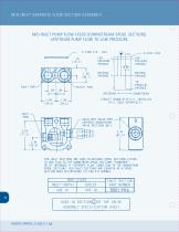
MID-INLET SEPARATE FLOW SECTION ASSEMBLY MID-INLET PUMP FLOW FEEDS DOWNSTREAM SPOOL SECTIONS. UPSTREAM PUMP FLOW TO LOW PRESSURE. INLET PORT OUTLET PORT CIRCUIT SHOWN WITH R.V. INSTALLED MID-INLET SECTIONS ARE USED IN-BETWEEN SPOOL SECTIONS EITHER TO ADD FLOW TO THE DOWNSTREAM SPOOL SECTIONS "COMBINER" OR TO INTRODUCE A "SEPARATE FLOW" CONDITION TO THE DOWNSTREAM SPOOL SECTIONS. MID-INLET SECTIONS ARE COUNTED AS A SPOOL SECTION WHEN DETERMINING TIE ROD KIT NUMBER. ASSEMBLY SPECIFICATION SHEET
Open the catalog to page 10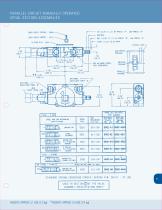
PARALLEL CIRCUIT MANUALLY OPERATED SPOOL SECTION ASSEMBLIES LOAD CHECK SPRING - 506.4 LOAD CHECK POPPET - 50 SPOOL SECTION ASSY. PART NUMBERS VALVE PORTS VALVE PORTS (SINGLE ACTING) * ONLY ONE AUX. PORT {"A" SIDE) DETENTED FLOAT STANDARD SPRING CENTERING FORCES (SPRING P/N: 5014) - 37 LBS. USED IN SECT I ON(5)0F THE VALVE ASSEMBLY SPECIFICATION SHEET WEIGHT: APPROX. 5.1 LBS. [2.3 kg] **WEIGHT: APPROX. 5.4 LBS. [2.4 kg]
Open the catalog to page 11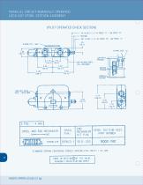
PARALLEL CIRCUIT MANUALLY OPERATED LOCK-OUT SPOOL SECTION ASSEMBLY (PILOT OPERATED CHECK SECTION! O-RING SIDE ■SAE «8 WORK PORTS STANDARD SPRING CENTERING FORCES (SPRING P/N: 5014) - 37 LBS. ASSEMBLY SPECIFICATION SHEET
Open the catalog to page 12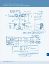
PARALLEL CIRCUIT HYDRAULIC REMOTE (OIL PILOT OPERATED) SPOOL SECTION ASSEMBLIES LOAD CHECK SPRING - 5064 LOAD CHECK POPPET - 5011 SAE *fc PILOT PORT (BOTH ENDS) WHEN PILOT PRESSURE IS APPLIED TO THIS PILOT PORT SECTION SENSES HI-PRESS. "A". LOW PRESS. "B". WHEN PILOT PRESSURE IS APPLIED TO OPPOSITE PILOT PORT SECTION SENSES HI-PRESS. "B". LOW PRESS. "A". WHEN NO PILOT PRESSURE IS APPLIED SECTION SENSES NEUTRAL. SPOOL SECTION ASSY. PART NUMBERS VALVE PORTS VALVE PORTS APPROXIMATE PILOT PRESSURE VS SPOOL TRAVEL: 20 PSI -- SPOOL STARTS TO SHIFT 80 PSI -- FLOW BEGINS AT WORK PORT 36.0 PSI -- FULL...
Open the catalog to page 13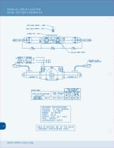
PARALLEL CIRCUIT ELECTRIC SPOOL SECTION ASSEMBLIES LOAD CHECK SPRING - 5064 LOAD CHECK POPPET - 5011 FEMALE CONNECTOR SOLENOID SPECIFICATIONS: TYPE: ON/OFF CONTINUOUSLY RATED USED IN SECTION (2) OF THE VALVE ASSEMBLY SPECIFICATION SHEET
Open the catalog to page 14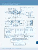
CONVENTIONAL CIRCUIT MANUALLY OPERATED SPOOL SECTION ASSEMBLIES (TANDEM) LOAD CHECK SPRING - 5064 LOAD CHECK POPPET - 5011 ^-AUTO KICK-OUT O-RING SIDE ■* SEE AUTO KICK-OUT FEATURE PAGE 28 (APPENDIX 1) SPOOL SECTION ASSY. PART NUMBERS VALVE PORTS VALVE PORTS STANDARD SPRING CENTERING FORCES (SPRING P/N: 5014) ■ 37 LBS. •*• REMOVE CAP FOR AUTO KICK-OUT ADJUSTMENTS. USE FLAT HEAD USED IN SECTION(|)OF THE VALVE ASSEMBLY SPECIFICATION SHEET WEIGHT: APPROX. 5.1 LBS. [2.3 kg] **WEIGHT: APPROX. 5.6 LBS. [2.5 kg]
Open the catalog to page 15All Husco International catalogs and technical brochures
 SCX180
32 Pages
 SCX300
1 Page
 VF1600e
1 Page
 VF1200
1 Page
 6000-valve
30 Pages
 6400-valves
1 Page
 6600-series
2 Pages
 7100-valve
15 Pages
 9210-valve
6 Pages
 9610-valve
1 Page
 PPCs and Joysticks
15 Pages
 HUSCO Hitch with EZ Select
2 Pages
 Hitch Control Valves
1 Page
 Header Control Valve
1 Page
 Suspension
1 Page
 HEC-808
2 Pages
 HVC
HVC1 Page
 EHPV
EHPV2 Pages
 Hitch Control
1 Page
 5000
500035 Pages
 VF1200e
1 Page
 VF1000
1 Page
 SCX120
32 Pages

- Water valve
- Regulating valve
- Electric valve
- Directional control valve
- Gate valve
- Piston actuator valve
- Oil valve
- Hydraulic valve
- Hydraulic directional control valve
- Flow control valve
- Spool hydraulic directional control valve
- Hydraulically-operated valve
- Plug valve
- Electrically-operated hydraulic directional control valve
- Remote control joystick
- Electro-hydraulic hydraulic directional control valve
- Pilot-operated hydraulic directional control valve
- Disc valve