LA, LB Linear Synchronous Motor
1 /3Pages
LA, LB Linear Synchronous Motor
1 /3Pages
Catalog excerpts

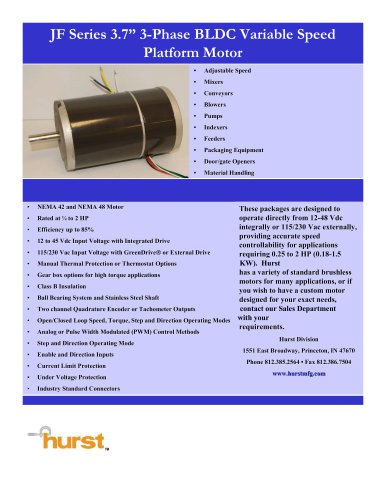
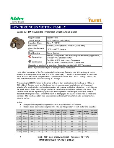
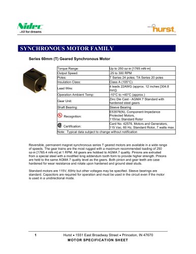
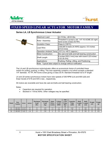
FIXED SPEED LINEAR ACTUATOR MOTOR FAMILY Series LA, LB Synchronous Linear Actuator Maximum Load: LA 10 lbs., LB 6.5 lbs. Threaded to accept a std. 1/4"-16 ACME 2G rightRotor Assembly: hand screw (Class 2G RH) Insulation Class: Class A (105°C) LAS/LBS 6 leads 24 AWG (approx. 8.5 inches Lead Wire: [215.9 mm]) Operation Ambient Temp: -10°C to +40°C (approx.) Motor Construction: Die cast end bells and ball bearing construction 8 inches [203.2 mm] max with travel 5.25 inches Shaft Length: [133.35 mm] Applications: Pushing, Pulling, Lifting, and Positioning Note: Typical data subject to change without notification The LA and LB synchronous motor/actuator offers an economical choice of controlled linear motion for pulling, pushing, or lifting. The rotor assembly contains a nut which accepts a standard 1/4" diameter, 16 TPI, RH Acme screw giving a Class 2G fit. Standard threaded rod is 8" length. LA and LB series synchronous motors have rotor speeds of 300 RPM (LA) and 600 (LB) and linear travels of 5/16 and 5/8 in./sec., respectively. All motors are reversible and have die cast end bells and ball bearing construction. Notes: • Capacitors are required for operation. • Stocked in 115Vac 60Hz. Other voltages may be specified. Part Number Input Power (watts) Full Load Temp. Rise °C Hurst 1551 East Broadway Street Princeton, IN 47670 MOTOR SPECIFICATION SHEET
Open the catalog to page 1
Hurst 1551 East Broadway Street Princeton, IN 47670 MOTOR SPECIFICATION SHEET
Open the catalog to page 2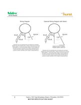
Wiring Diagram Optional Wiring Diagram with Switch Capacitors are non-polarized and must always be connected between the red and black leads. Always connect the (2) coil blue leads together. Connect the power supply to the blue leads and red lead to produce clockwise (CW) rotation viewing shaft end. Connect the power supply to the blue leads and black lead to produce counter-clockwise (CCW) rotation viewing shaft end. SINGLE-POLE DOUBLE THROW (SPDT) SWITCH Capacitors are non-polarized and must always be connected between the red and black leads. Always connect the (2) coil blue leads together....
Open the catalog to page 3All Hurst catalogs and technical brochures
 BRUSHLESS DC MOTOR FAMILY
7 Pages
 HURST® 2008 Catalog
55 Pages