
- Catalogs
- Huco Engineering Industries
- Flexible Couplings

Flexible Couplings

Flexible Couplings
Huco Dynatork offers a wide range of flexible couplings for precision industrial and commercial applications. These couplings are essential for the dynamic response of drive systems, providing various levels of torsional stiffness, vibration dampening, and low bearing loads. The product range includes precision, beam, and general-purpose couplings, each tailored for specific applications.
Flex B Bellows, Flex K Large Bellows, and Flex M Disc type couplings are designed for high-end applications such as servo drives, pulse generators, and machine tools. They offer excellent kinematic properties with varying stiffness, radial compensation, and axial motion capabilities.
Available in Step Beam, Single Beam, Three Beam, and Six Beam configurations, these couplings are suitable for stepper and servo drives, encoders, and light-duty power transmission applications. They provide flexibility and torsional rigidity.
Oldham couplings are versatile for stepper drives and positioning slides, while Uni-Lat models are ideal for encoders and small positioning slides. Flex P units are used in light power drives and small generators.
Vari-Tork™ friction clutches allow for controlled slippage to protect equipment and personnel, suitable for small drive applications.
When selecting flexible couplings, consider factors such as torsional stiffness, backlash, torque, life expectancy, shaft attachment type, and misalignment requirements. Service factors should be adjusted based on load conditions and environmental factors.
Ensure shafts are free of burrs and damage before installation. Couplings should be installed without applying forces that exceed permissible offsets. Single-stage couplings provide radial support, while two-stage couplings are used when both shafts are fully supported by bearings.
1. Ensure the coupling is in its natural state, neither extended nor compressed.
2. Align the second shaft with the first using a straight edge and feeler gauges or a dial indicator.
3. Secure the second shaft and re-check alignment, ensuring it is within permissible offsets.
4. Secure one hub by tightening each screw alternately, then repeat for the second hub.
- Single-stage and two-stage couplings are available, with specific applications for each.
- Precision high couplings have limited permissible flexure and can be damaged by careless handling.
- No axial forces are permitted across the membranes when fitting Huco-Flex M couplings.
- Bellows couplings are more tolerant of axial motion but should not exceed permissible limits.
- For partially supported shafts, specific installation steps are outlined for both blind hub and thro’ hub configurations.
- Gap gauges are used to ensure proper spacing and alignment.
- Various coupling sizes and their corresponding gap gauges are specified.
- Clearances are set to allow for thermal shaft growth and/or end-float.
- Radial support requires shafts to be fully supported by two bearings with minimal overhang.
- Hubs are made from Al. Alloy 2014T6 with a clear anodised finish.
- Bellows are constructed from spring quality stainless steel.
- Joint assembly uses copper C106, heat-treated zinc plate, and clear passivate.
- Fasteners are made from alloy steel, black oiled.
- The document provides detailed performance tables for different coupling types, including peak torque, torsional stiffness, and compensation values.
- Temperature range for operation is specified as -40ºF to +248ºF (-40°C to +120°C).
- Avoid gratuitous flexure in any direction to prevent damage.
- Keyways with interference fits are not recommended.
- Ensure couplings are not end-loaded to maintain functionality.
- Material and Construction: The convolutions are formed by electrolytic deposition of nickel, ensuring stress-free and controlled wall thickness. Hubs are made from aluminum alloy, and fasteners are alloy steel.
- Performance Characteristics: High torsional stiffness allows for rotational positional integrity while accommodating lateral and angular misalignment due to low spring rates.
- Temperature Range: -50ºF to +248ºF (-50°C to +120°C).
- Applications: Primarily used in instrumentation and sensitive applications.
- Material and Construction: Hubs and spacers are made from aluminum alloy with a clear anodized finish. Membranes are made from spring quality stainless steel, heat-treated for durability.
- Performance Characteristics: Designed for use with drive shafts, offering flexibility for radial misalignment and lower bearing loads.
- Temperature Range: -40ºF to +248ºF (-40°C to +120°C).
- Applications: Suitable for use in pairs or with floating shafts, providing precise alignment and accommodating greater radial misalignment.
- Types: Includes Sliding Disc (Oldham) and Universal Lateral (Uni-Lat) couplings.
- Features: Backlash-free up to 108 turns, capable of tolerating large misalignments, and electrically isolating.
- Applications: Used for pulse generator drives and stepper-driven positioning stages.
- Dimensions and Order Codes: Detailed tables provide dimensions, order codes, and performance metrics for various coupling sizes.
- Performance Metrics: Includes torque, angular and radial misalignment compensation, and nominal spring rates.
- Load capacity depends on application conditions.
- Sizes indicated in parenthesis are metric (mm).
The document provides detailed specifications for various types of couplings, including Oldham, Uni-Lat, and Beam couplings. It specifies the materials used, such as brass, aluminum, and stainless steel, and the finishes applied, like Irridite NCP and anodized finishes. The document also outlines the dimensions, torque capacities, and compensation capabilities for different coupling sizes.
Installation procedures are briefly mentioned, emphasizing the importance of setting axial compensation during installation and ensuring electrical isolation between shafts exceeding 3kV. The document advises selecting a coupling size where peak torque exceeds the application torque multiplied by a service factor.
Performance metrics are provided for couplings at 20°C with standard acetal discs. The document details peak torque values, maximum compensation at 3000 rpm, angular and radial offsets, and torsional stiffness. It highlights that load capacity depends on application conditions and advises consulting additional pages for detailed conditions.
The document recommends observing given values for maximum backlash-free life and ensuring that shafts do not penetrate beyond specified lengths during operation. It also suggests using specific coupling references for combining different bore sizes.
The tables provide comprehensive data on coupling dimensions, including diameter, length, bore sizes, moment of inertia, mass, and torque capacities. They also list the materials and finishes for each coupling type, along with the corresponding fasteners and their specifications.
- Ensure peak torque exceeds application torque x service factor.
- Couplings provide up to 1mm radial and 10° angular compensation.
- Electrical isolation between shafts should be greater than 3kV.
- Load capacity is contingent on specific application conditions.
The document provides detailed specifications for various mechanical components, including durometers, couplings, and universal joints. The durometer is specified as Shore 'A' hardness. Coupling sizes range from 1/8” to 5/8” with specific bore references and tolerances. The materials used include aluminum alloys, cast aluminum, polyurethane, and alloy steel, with temperature ranges specified for different components.
Instructions are provided for customizing teleshafts, including cutting tubes to achieve desired lengths and fitting nose bushes to eliminate torsional free play. The document outlines the empirical method for customizing teleshafts based on retracted length.
Standard bores and tolerances are specified for various sizes, with detailed dimensions and order codes provided for each component. The document also specifies the maximum rotational speed and temperature ranges for different materials and finishes.
Performance metrics such as peak torque, static break torque, torsional rate, and stiffness are detailed for both single and double joints. Recommendations for maintaining constant velocity ratios in universal joints are provided, including correct orientation and equal working angles.
The document lists materials such as steel, stainless steel, acetal, and brass for different components, with finishes like zinc plating and clear passivation.
Tables provide detailed dimensions, torque values, and performance metrics for various sizes of couplings and universal joints. The document includes order codes and specifications for customizing teleshafts and universal joints.
Key parameters include torque capacities, temperature ranges, material specifications, and customization procedures. The document emphasizes the importance of correct joint orientation and working angles to maintain performance.
- Velocity: Conversions between feet per minute, feet per second, and inches per second.
- Length: Conversions between millimeters, meters, inches, feet, yards, kilometers, and miles.
- Torque: Conversions between Newton meters, Newton centimeters, kilogram-force meters, pound-force feet, pound-force inches, and ounce-force inches.
- Power: Conversions between kilowatts, PS, horsepower, kilogram-force meters per second, and foot-pound-force per second.
- Moment of Inertia: Conversions between kilogram meter squared, kilogram-force meter squared, pound-foot squared, and other related units.
- Wichita Clutch: Pneumatic clutches and brakes.
- Warner Linear: Linear actuators.
- Formsprag Clutch: Overrunning clutches and holdbacks.
- Ameridrives Couplings: Mill spindles, Ameriflex, and Ameridisc couplings.
- Guardian Couplings: Engineered flywheel couplings and flexible shaft couplings.
- Matrix International: Electromagnetic clutches and brakes.
- Kilian Manufacturing: Engineered bearing assemblies.
- Bauer Gear Motor: Geared motors.
- Boston Gear: Enclosed and open gearing, electrical and mechanical components.
Catalog excerpts

ALTRA INDUSTRIAL MOTION ucoDynatork An Altra Industrial Motion Company
Open the catalog to page 1
Huco Dynatork offers a wide variety of couplings for precision industrial and commercial applications worldwide. Selecting the right shaft coupling can be the difference between a drive system that provides the required dynamic response and one that is catastrophic. The application constraints lead engineers towards products that have different levels of torsional stiffness, vibration dampening, backlash, and low bearing loads. Huco can respond quickly with a wide variety of couplings such as general purpose, beam style, and precision couplings suitable for highly reliable applications. Precision...
Open the catalog to page 2
General Purpose Couplings Oldham couplings are designed for use in stepper drives and most applications including positioning slides, pumps, actuators, etc. Uni-Lat models are ideal for encoder, resolver, tachometers, potentiometer drives, as well as small positioning slides, dosing pumps, and general light drives. Flex P units can be utilized in light power drives, pumps and small generators. Friction Clutches Vari-Tork™ friction clutches allow slippage when the torque being transmitted reaches a pre-determined threshold. Used in all types of small drives to help protect personnel and equipment....
Open the catalog to page 3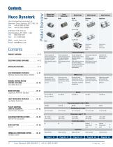
Huco Engineering Industries Ltd. ^ 440 North Fifth Avenue Chambersburg, PA 17201 - USA Tel: (888) 829 6637 “O Membrane, Stainless Steel Bellows, Ni Bellows Huco-Oldham & Uni-Lat Single Beam, Multi-Beam, Step Beam Jaw (Spider), Double Loop Huco-Pol & Huco Teleshafts Huco Vari-Tork, Slip Clutches
Open the catalog to page 4
Building an Ordering Part Number is fast and easy using the Specifications and Bore Size charts on each product page. Simply select the coupling type, coupling size and two bore sizes you require (always place smaller bore first). Always include (.) in Part Number. Ordering Number System Example: 536.20.1418 The following key factors should always be considered when specifying flexible shaft couplings: • Torsional Stiffness • Backlash • Torque • Life • Shaft Attachment Type • Misalignment Requirements Service Factors • Torque capacity values shown in the coupling specification charts assume uniform...
Open the catalog to page 6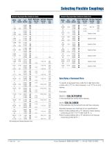
Selecting Flexible Couplings Metric Inch Inch Round Metric keys Inch keys Keywayed I I bore key size key size bore mm fraction decimal code w x h w x h code Metric Inch Inch Round Metric keys Inch keys Keywayed I I bore key size key size bore mm fraction decimal code w x h w x h code Specifying a Keywayed Bore To specify a keywayed bore, prefix the 2-digit bore code number with a “P” for metric keyways or an “R” for an inch keyway. Examples: Metric: 538.34.P28P28 In this example both bores have a keyway. Inch: 538.34.24R36 In this example only the second...
Open the catalog to page 7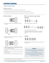
Installing Couplings Flexible Coupling Types General instructions 1. Ensure that shafts are free of burrs, damage, or foreign matter, and can penetrate the bores. 2. nstall the coupling by holding the shaft and the related hub, rotating it back and forth as you progress it along the shaft. I 3. Do not apply any forces that cause extension, compression or lateral displacement of the coupling beyond its permissible offsets. Normal installation When to use single & two-stage couplings Single-stage a) Position and secure the larger of the 2 shafts (if different) and progress the coupling onto it....
Open the catalog to page 8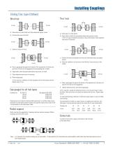
Sliding Disc type (Oldham)Blind hub a) Slide hubs on to both shafts. b) Align shafts to within the permissible offsets and position to leave minimum gap 2 between terminations. Secure both shafts, check alignment and correct if necessary. c) Position R/H hub with inboard face flush with shaft termination and tighten screws. d) Slide disc radially on to the tenons of the R/H hub. Ensure the disc is fully seated. d) Place a gap gauge flat against the bottom of the exposed slot in the disc and push the L/H hub into full engagement by manipulating the L/H shaft. e) Align shafts within the permissible...
Open the catalog to page 9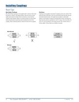
Installing Couplings Beam Type Relief Under The Beams Most Multi-Beam couplings can be supplied with or without relief under the beams as shown in the diagrams below. When the drive or driven shafts extend under the beams relief is essential to ensure that the coupling remains flexible. Where non-relieved versions are used, shafts must not be allowed to penetrate under the beamed section of the coupling. Unless otherwise specified, relieved versions will be supplied. Pilot Bores Couplings can be supplied ‘pilot bored’ for opening out by the customer. Pilot bores are plain drilled holes, which...
Open the catalog to page 10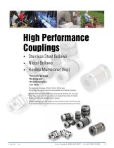
High Performance Couplings • Stainless Steel Bellows • Nickel Bellows • Flexible Membrane (Disc) • Torsionally rigid design • No moving parts • All-metal construction The operating principles of Flex B, Flex K, Flex Ni and Flex M offer the highest performance available with flexible couplings. With excellent kinematic properties and torsional stiffness of a very high order, they are suitable for servo drives and satisfy the criteria for highly dynamic position and velocity control systems. Bellows couplings have the greater torsional stiffness while Flex M have the more tolerant flexural system...
Open the catalog to page 11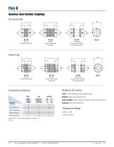
Flex-B Stainless Steel Bellows Couplings Set screw hubs L L1 Ref. 530 Short type for precisely aligned shafts Ref. 532 Long type for greater angular offsets or axial motion Ref. 534 Stretched type for greater radial misalignment and lower bearing loads Ref. 536 Short type for precisely aligned shafts Ref. 538 Long type for greater angular offsets or axial motion Ref. 540 Stretched type for greater radial misalignment and lower bearing loads Materials & Finishes Comparative properties Hubs: Al. Alloy 2014T6 and Clear anodised finish Type Bellows: Spring quality stainless steel Joint assembly:...
Open the catalog to page 12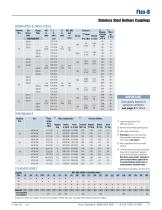
Size Screw Hubs in. in. STANDARD BORES Load capacity depends on application conditions: see page 4for details © Length of supported thro' bore. Shafts can near-butt. © Maximum recommended tightening torque. © Values apply with max bores. © Peak torque. Select a size where Peak Torque exceeds the application torque x service factor. (see page 4) © Max. compensation values are mutually exclusive. © Torsional stiffness values apply at 50% peak torque with no misalignment, measured shaft-to-shaft with largest standard bores. Note that in some vendors' catalogs the given torsional stiffness...
Open the catalog to page 13All Huco Engineering Industries catalogs and technical brochures
 Nylon Sleeve Gear Couplings
4 Pages
 Beam Couplings
14 Pages
 Dynatork Service Kits
1 Page
 Industrial Couplings
8 Pages
 Multi-Beam Couplings
1 Page
 Spacers, Pillars and Stand-offs
12 Pages
 Air Motors
32 Pages
 Rod End Bearings & Linkages
28 Pages
 Belts and Pulleys
16 Pages
 Universal Joints
16 Pages
 Torque limiters
4 Pages
