- Catalogs
- HUBA CONTROL
- Flow sensor 212 with display 0.5 ... 150 l/min
- Company
- Products
- Catalogs
- News & Trends
- Exhibitions
Flow sensor 212 with display 0.5 ... 150 l/min
1 /7Pages

Flow sensor 212 with display 0.5 ... 150 l/min
1 /7Pages
Catalog excerpts

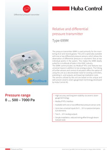
Vortex flow sensor Flow sensor for liquid media with display Type 212 The flow sensor type 212 is based on the Vortex trail principle. This flow sensor convinces due to the additional digital indicating device which shows the flow rate and the media temperature. The type 212 is available with and without temperature measurement. With no moving parts the flow sensor is not sensitive to debris, has marginal pressure loss and high accuracy. + Flow measuring with immediate display of flow measuring range and medium temperatur + Temperature non-sensitive flow measuring principle + Excellent media resistance (measuring element not in contact with the media) + CE conformity + Wide application temperature range + Marginal loss of pressure + Measuring element not sensitive to debris + Direct temperature measurement in the medium + Drinking water approval Huba Control Type 212 | Technical data subject to change | Edition 09/2020
Open the catalog to page 1
Technical overview Flow measurement Measuring principle Vortex Measuring range Nominal diameters Accuracy (via temperature) at < 50% fs (water) Accuracy (via temperature) at > 50% fs (water) Response time Piezoelectric sensor element 0.5 ... 150 l/min DN 6 / 8 / 10 / 15 / 20 / 25 < 1% fs < 2% measuring value Signal delay < 2s Response time < 500 ms Display update rate < 500 ms Measuring range Accuracy 4 ... 14.5 mA Calculation temperature Operating conditions Medium Water Media Ambient Temperature Storage (for lifetime) Max. pressure and medium temperature (for lifetime) (max. test pressure)...
Open the catalog to page 2
Nominal diameters dependent variables Nominal diameters Measuring range Flow range Characteristic line formula current output QV = KI * (IOUT - 4 mA) Pressure drop Legend Volume flow rate QV Coefficient current output KI IOUT Current Order code selection table 212. X X X X X X X X X Version Flow 9 4 Flow and temperature 8 5 DN 6 0.5 ... 10 l/min. (with temperature on request) 9 0 6 4 K,G DN 8 0.9 ... 15 l/min. 0 8 DN 10 1.8 ... 32 l/min. 1 0 Nominal diameters and DN 10 2.0 ... 40 l/min. 1 1 flow rate DN 15 3.5 ... 50 l/min. 1 5 DN 20 5.0 ... 85 l/min. 2 0 DN 25 9.0 ... 150 l/min. 2 5 K,G Q: 4...
Open the catalog to page 3
Huba Control Type 212 | Technical data subject to change | Edition
Open the catalog to page 4
Admissible locking torque DN6/8/10 G½ inside thread Geometry of customers connection tube DN 8, 10, 15, 20 O-ring Huba Control Type 212 | Technica
Open the catalog to page 5
Tube mounting instructions Consider the following to ensure the correct function of the sensor. • Only diameter changes from large to small are allowed. • Avoid repeated elbows in the same level at entryside minimum 5xDN for alternative elbows minimum 0.5xDN for recommended 90º elbow with min. R 1.8xDN Pin 3 - not connected Connect pin 1 and pin 4 to ensure the power supply of the internal electronic. Huba Control Type 212 | Technical data subject to change | Edition 09/20
Open the catalog to page 6
Huba Control AG Headquarters Schweiz Industriestrasse 17 CH-5436 Würenlos Telefon Niederlassung Deutschland Vestiging Nederland Succursale France Branch Office United Kingdom Unit 13 Berkshire House, County Park Technopôle Forbach-Sud Business Centre, Shivenham Road
Open the catalog to page 7All HUBA CONTROL catalogs and technical brochures
 Pressure sensor 515
6 Pages
 506 Pressure sensor
5 Pages
 PRODUCT OVERVIEW
23 Pages
 410 Force cell
3 Pages
 OEM Flowsensor for Liquids
8 Pages


- Flowmeter
- Volume flow monitor
- Liquid flow monitor
- Force sensor
- LCD display panel
- Pressure transmitter
- Tension/compression force transducer
- Analog pressure transmitter
- Pressure switch
- Pressure probe
- Precision flow meter
- Waterproof pressure transmitter
- Membrane pressure transmitter
- Stainless steel pressure transmitter
- Relative pressure transmitter
- In-line flow meter
- Beam type force sensor
- Mechanical pressure switch
- Digital pressure transmitter