WSL, WDL
1 /49Pages

WSL, WDL
1 /49Pages
Catalog excerpts

<§>HmW □ L De-energized Tap Changer Technical Instructions HM0.154.602 Shanghai Huaming Power Equipment Co.,Ltd.
Open the catalog to page 1
<§>Hm General
Open the catalog to page 2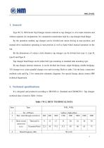
<§>Hm 1. General Type W^L Off-Circuit Tap Changer (herein referred as tap changer) is of in-tank structure and without separate oil compartment. It is mounted to transformer tank by a tap changer head flange. By the operation method, tap changer can be divided into motor driving at man position, and manual drive mechanism operating at man position as well as hand wheel manual operation on the top. By the dimensions of contact circle diameter, tap changer can be divided into type A, type B, type D and Type E. Tap changer head flange can be either bell type mounting or standard tank mounting type....
Open the catalog to page 3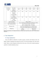
Remark: The tap changer can be designed and produced according to special requirements, please contact with HM Technical Department. 3. Type designation 3.1. Type explanation Due to the different combinations of number of phases, maximum rated through current, the highest voltage for equipment and connection, type W^L off-circuit tap changer comes with various models. Hence, the type designation shall provide all the above all the above technical parameters and below is detailed explanation in Fig. 1.
Open the catalog to page 4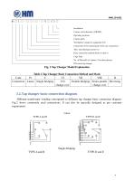
Installation Contact circle diameter (A/B/D/E) Operating positions Contact pitch The highest voltage for equipment (kV) Connection (Y-for neutral point. D-for any connection) Max. rated through current (A) Basic connection method (Refer to table 1) Cage Type No. of Phases(D for I phase, S for three phases) Off-circuit tap changer Fig. 1 Tap Changer Model Explanation Table 2 Tap Changer Basic Connection Method and Mark 3.2. Tap changer basic connection diagram Different transformer winding corresponds to different tap changer basic connection diagram. Fig.2 shows commonly used connections. It...
Open the catalog to page 5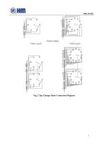
Fig. 2 Tap Changer Basic Connection Diagram
Open the catalog to page 6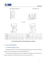
<§>Hm Series-parallel change-over Y-D change-over Fig. 2 Tap Changer Basic Connection Diagram (Continued) 4. Terms and definitions 4.1. Rated through-current Rated through current Iu: The current flowing through the tap changer toward the external circuit, which can be carried continuously while meeting the requirement. The maximum rated through current Ium: The highest rated through current for which the tap changer is designed for and which forms the basis for all current related tests.
Open the catalog to page 7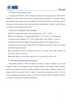
4.2. Short circuit current test According to IEC 60214-1: 2003, all contacts continuously carrying the current shall be able to withstand 2s (±10%) short circuit test current without melting, deformation or mechanical damage. Meanwhile the starting peak current value shall be 2.5 (±5%) times of the root means square value of rated short circuit test current. Refer the short circuit test current values to Table 1 Type WSL Series of Off-Circuit Tap Changer Technical Data. 4.3. Service condition of tap changers 4.3.1. Service temperature range of the tap changer in oil is -25°C~ +100℃. 4.3.2. Service...
Open the catalog to page 8
a: Between max. and min. taps of the same phase b: Between any winding taps of different phases or between start and end of the same tap winding for double-bridging
Open the catalog to page 9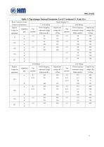
<§>Hm Table 3: Tap changer Internal Insulation Level (Continued 1) (Unit: Kv)
Open the catalog to page 10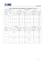
<§>Hm Table 3: Tap changer Internal Insulation Level (Continued 2) (Unit: Kv)
Open the catalog to page 11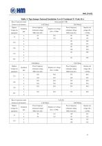
<§>Hm Table 3: Tap changer Internal Insulation Level (Continued 3) (Unit: Kv)
Open the catalog to page 12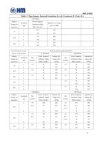
Basic Connection mode Contact circle diameter
Open the catalog to page 13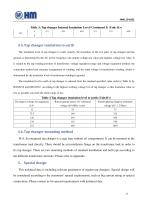
<§>HmTable 3: Tap changer Internal Insulation Level (Continued 5) (Unit: Kv) 2-5 4.5. Tap changer insulation to earth The insulation level of tap changer to earth, namely, the insulation of the live parts of tap changer and the ground, is determined by the AC power frequency one-minute voltage test value and impulse voltage test value. It is related to the tap winding position of transformer, voltage regulation range and voltage regulation method, the connection method and structure arrangement of winding, and the rated voltage of transformer winding, which is determined by the insulation level...
Open the catalog to page 14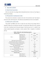
»wm6. Operation method 6.1. Hand wheel operation Drive the main shaft of tap changer directly through hand wheel on the top of tap changer to realize the tap changing. 6.2. Manual drive mechanism at side The manual drive mechanism is mounted on the side of the transformer tank. Tap changer is driven by the drive shaft and gear box. The dimension and installation are shown in the Appendix. 6.3. Motor drive unit at side Using CMA7 and SHM-D motor drive to realize the motor driving for tap changer. Refer to Appendix of Motor drive unit dimension and table 5 for technical data. Motor drive unit is...
Open the catalog to page 15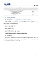
7. Position indicator 7.1. HMC-3W De-energized tap changer position indicator HMC-3W DETC position indicator is designed for CMA7 motor drive unit. It can be used to indicate the DETC position remote room. HMC-3W technical parameters: Working voltage: 220V AC Power frequency: 50 Hz Maximum operation positions: 39 Environment temperature: -10°C ~ +40°C Note: for special power supply, please inform when ordering. 8. Accessories Bevel gearbox is applicable for connection of horizontal shaft of tap changer and vertical shaft of the motor drive unit, by which transferring the driving torque from motor...
Open the catalog to page 16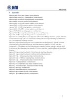
9. Appendix Appendix 1 600-1000A Linear regulation, overall dimension Appendix 2 600-1000A 252kV Linear regulation, overall dimension Appendix 3 600-1000A Single-bridging regulation, overall dimension Appendix 4 600-1000A Y-D regulation, overall dimension Appendix 5 600-1000A Double-bridging regulation, overall dimension Appendix 6 600-1000A Series-parallel regulation, overall dimension Appendix 7 600-1000A Reversing regulation, overall dimension Appendix 8 600-1000A 252kV reversing regulation, overall dimension Appendix 9 1000-2000A Reversing regulation, overall dimension Appendix 10 Installation...
Open the catalog to page 17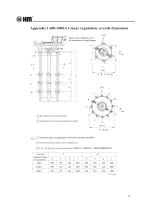
Appendix 1 600-1000A Linear regulation, overall dimension X Please refer to Appendix 12-21 for dimensions of head flanges X Bevel gearbox transmission shaft Z Orientation of bevel gearbox transmission shaft 1 Note: Generally type A is applicable to the current of less than 800A 2 Connect dimension. Please refer to Appendix 20 3 A、B、D and E type cage outer diameters: Φ350mm、Φ500mm、Φ600mm和Φ750mm Conection Highest Voltage for equipment
Open the catalog to page 18All HUAMING POWER EQUIPMENT CO., LTD. catalogs and technical brochures
 TYPE WDG/WLG/WSG
39 Pages
 SHZV
SHZV100 Pages
 HWV
HWV34 Pages
 CM2
CM270 Pages
 CV2
CV230 Pages
 CZ
CZ24 Pages
 CVT
CVT10 Pages
 TYPE CV & SV
34 Pages
 CMD
CMD59 Pages
 TYPE CM
83 Pages