

TYPE CM

TYPE CM
The Type CM Oil-Immersed On-Load Tap Changer (OLTC) is designed for oil-immersed transformers, featuring a diverter switch and a tap selector. It supports three-phase operation at the neutral point of a star connection or single-phase operation for selectable winding connections.
The OLTC adheres to IEC60214-1 (2003) standards. Key specifications include a maximum rated through-current of 500A to 1500A, rated frequency of 50 or 60 Hz, maximum rated step voltage of 3300V, and rated step capacity of 1400 kVA to 3500 kVA. It has a mechanical life of at least 800,000 operations and a contact life of at least 200,000 operations.
Model designation is based on parameters such as phase number, maximum rated current, highest voltage, insulation level, and connection type, detailed in diagrams within the document.
Key terms include through current, step voltage, rated step capacity, breaking capacity, electrical life of arcing contact, and short-circuit current test.
Operational conditions include an oil temperature range of -25°C to 105°C, ambient air temperature range of -25°C to 40°C, and installation site requirements free of heavy dust, explosive or corrosive gas.
Internal insulation is categorized into four levels: B, C, D, and DE, with varying withstand voltages between taps and phases.
The document outlines insulation requirements per IEC-60214-1(2003), emphasizing the importance of insulation level to ground.
Detailed technical data for the Type CM OLTC includes rated voltage stress on tap winding and insulation levels, with tables specifying voltage withstand values for different tap selector sizes.
The OLTC can be mounted using a mounting flange, suitable for both standard tank and bell-type configurations.
For high voltage or wide regulation range transformers, tie-in resistors are specified to manage potential differences and prevent flashover.
The OLTC can be operated by SHM-III or CMA7 motor drive units, with technical data provided for power, voltage, and mechanical endurance.
The HMK8 controller is used for remote control of the motor drive unit, with the HMC-3C position indicator providing step indication and remote control functions.
Accessories include bevel gear units, protective relays, pressure relief devices, and oil filter plants to enhance OLTC reliability and safety.
Detailed dimensions and installation instructions for various OLTC components and configurations are provided.
The document provides technical data and specifications for CM oil-immersed on-load tap changers, focusing on models with multiple coarse and fine tap selectors.
The CM on-load tap changer is designed with 106 steps for multiple and fine regulation, with performance consistent with regular CM tap changers.
Technical data for different models, such as CM III 500Y/600Y, CM I 500/600, CM I 800, and CM I 1200/1500, are provided with dimensions in millimeters.
Numerous tables and diagrams show operating positions and connection diagrams for various CM models, providing a visual guide for installation and operation.
Tables provide detailed information on voltage regulation positions, fine tap positions, and coarse tap positions for each model.
Contact details for Shanghai Huaming Power Equipment Co., Ltd. are provided for further inquiries.
Catalog excerpts

TECHNICAL DATA TYPE CM OIL-IMMERSED ON-LOAD TAP CHANGER HM0.154.301 SHANGHAI HUAMING POWER EQUIPMENT CO., LTD.
Open the catalog to page 1
TYPE CM OIL-IMMERSED ON-LOAD TAP CHANGER TECHNICAL DATA 1. General ⋯⋯⋯⋯⋯⋯⋯⋯⋯⋯⋯⋯⋯⋯⋯⋯⋯⋯⋯⋯⋯⋯⋯⋯⋯⋯⋯⋯⋯⋯⋯⋯⋯⋯⋯⋯⋯⋯⋯⋯⋯⋯⋯⋯⋯⋯3 2. Technical specification⋯⋯⋯⋯⋯⋯⋯⋯⋯⋯⋯⋯⋯⋯⋯⋯⋯⋯⋯⋯⋯⋯⋯⋯⋯⋯⋯⋯⋯⋯⋯⋯⋯⋯⋯⋯⋯⋯⋯⋯4 3. Model designation ⋯⋯⋯⋯⋯⋯⋯⋯⋯⋯⋯⋯⋯⋯⋯⋯⋯⋯⋯⋯⋯⋯⋯⋯⋯⋯⋯⋯⋯⋯⋯⋯⋯⋯⋯⋯⋯⋯⋯⋯⋯5 4. Terms and definitions ⋯⋯⋯⋯⋯⋯⋯⋯⋯⋯⋯⋯⋯⋯⋯⋯⋯⋯⋯⋯⋯⋯⋯⋯⋯⋯⋯⋯⋯⋯⋯⋯⋯⋯⋯⋯⋯⋯⋯⋯7 5. Special designs⋯⋯⋯⋯⋯⋯⋯⋯⋯⋯⋯⋯⋯⋯⋯⋯⋯⋯⋯⋯⋯⋯⋯⋯⋯⋯⋯⋯⋯⋯⋯⋯⋯⋯⋯⋯⋯⋯⋯⋯⋯⋯10 6. Motor drive unit ⋯⋯⋯⋯⋯⋯⋯⋯⋯⋯⋯⋯⋯⋯⋯⋯⋯⋯⋯⋯⋯⋯⋯⋯⋯⋯⋯⋯⋯⋯⋯⋯⋯⋯⋯⋯⋯⋯⋯⋯⋯⋯12 7. Controllers for On-Load tap changer ⋯⋯⋯⋯⋯⋯⋯⋯⋯⋯⋯⋯⋯⋯⋯⋯⋯⋯⋯⋯⋯⋯⋯⋯⋯⋯⋯⋯⋯⋯⋯⋯⋯13 8. OLTC accessories⋯⋯⋯⋯⋯⋯⋯⋯⋯⋯⋯⋯⋯⋯⋯⋯⋯⋯⋯⋯⋯⋯⋯⋯⋯⋯⋯⋯⋯⋯⋯⋯⋯⋯⋯⋯⋯⋯⋯⋯⋯13 9. Appendixes⋯⋯⋯⋯⋯⋯⋯⋯⋯⋯⋯⋯⋯⋯⋯⋯⋯⋯⋯⋯⋯⋯⋯⋯⋯⋯⋯⋯⋯⋯⋯⋯⋯⋯⋯⋯⋯⋯⋯⋯⋯⋯⋯⋯14...
Open the catalog to page 2
TYPE CM OIL-IMMERSED ON-LOAD TAP CHANGER TECHNICAL DATA 9.27 Protective relay, overall & installation dimensions⋯⋯⋯⋯⋯⋯⋯⋯⋯⋯⋯⋯⋯⋯⋯⋯⋯⋯⋯⋯⋯⋯⋯⋯⋯⋯⋯42 9.28 CM OLTC with multiple coarse and fine tap selector, connection drawing⋯⋯⋯⋯⋯⋯⋯⋯⋯⋯⋯⋯⋯⋯⋯⋯⋯43 9.29 CM III 500Y/600Y with multiple coarse and fine tap selector, overall dimensions⋯⋯⋯⋯⋯⋯⋯⋯⋯⋯⋯⋯⋯⋯44 9.30 CM I 500/600 with multiple coarse and fine tap selector, overall dimensions⋯⋯⋯⋯⋯⋯⋯⋯⋯⋯⋯⋯⋯⋯⋯⋯45 9.31 CM I 800 with multiple coarse and fine tap selector, overall dimensions⋯⋯⋯⋯⋯⋯⋯⋯⋯⋯⋯⋯⋯⋯⋯⋯⋯⋯46 9.32 CM I 1200/1500 with multiple coarse and fine tap selector, overall...
Open the catalog to page 3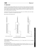
1. General Type CM On-Load Tap Changer (hereinafter referred as CM or CM OLTC) is a typical combined-structure tap changer applicable in oil-immersed transformer, comprising of two major parts: diverter switch and tap selector. The CM OLTC is put in transformer oil tank and its diverter switch has a separate oil compartment from transformer tank, while tap selector, together with transformer windings, is completely laid inside the tank. OLTC’s installation is divided into two types - standard tank flange and bell-type flange. Three-phase CM OLTC could be used at neutral point of star-connection,...
Open the catalog to page 4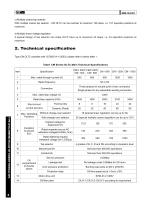
<i>Hm_ c) Multiple coarse tap selector With multiple coarse tap selector , CM OLTC can be reached to maximum 106 steps, i.e. 107 operation positions at maximum. d) Multiple linear voltage regulation A special design of tap selector can make OLTC have up to maximum 33 steps, i.e. 34 operation positions at maximum. 2. Technical specification Type CM OLTC complies with IEC60214-1 (2003), please refer to below table 1. Tabel CM Series OLTC Main Technical Specifications TYPE CM OIL-IMMERSED ON-LOAD TAP CHANGER TECHNICAL DATA
Open the catalog to page 5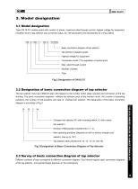
3. Model designation 3.1 Model designation Type CM OLTC models varies with number of phase, maximum.rated through current, highest voltage for equipment, insulation level of tap selector and connection ways, etc.The parameters are represented as in Fig.2 below. CM III - 600 Y / 126 D - 10193W Basic connection diagram of tap selector Tap selector insulation grade Highest voltage for equipment Connection mode: Y for regulation at neutral point Max .rated through current Number of phase Type Fig.2 Designation of CM OLTC 3.2 Designation of basic connection diagram of tap selector The tap selector...
Open the catalog to page 6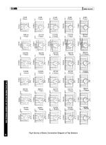
TYPE CM OIL-IMMERSED ON-LOAD TAP CHANGER TECHNICAL DATA Fig.4 Survey of Basic Connection Diagram of Tap Selector
Open the catalog to page 7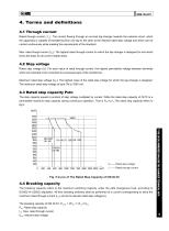
4. Terms and definitions 4.1 Through current Rated through current ( Iu) : The current flowing through an on-load tap-changer towards the external circuit, which the apparatus is capable of transferring from one tap to the other at the relevant rated step voltage and which can be carried continuously while meeting the requirements of the standard. Max. rated though-current (Ium): The highest rated through-current for which the tap-changer is designed for and which forms the basis for all current related tests. 4.2 Step voltage Rated step voltage (Ui): For each value of rated through-current,...
Open the catalog to page 8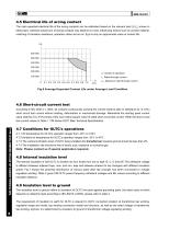
4.5 Electrical life of arcing contact The main expected electrical life of the arcing contacts can be estimated based on the relevant load (Iu/Ium) shown in below fig.6, whereas actual burn of arcing contacts may depend on many influencing factors such as contact material, matching of transition resistance, operation status and so on, fig.6 is only an approximate value of contact life. n: number of operation Iu: Rated through current Ium: Maximum rated through current Fig.6 Average Expected Contact Life under Average Load Condition 4.6 Short-circuit current test According to IEC 60214-1: 2003,...
Open the catalog to page 9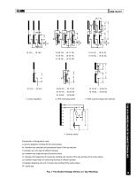
2. With reversing switch 3. With coarse change-over selector Explanation of designation code: a: across regulation winding for the same phase a1: between any selected and preselected taps of the tap selector b: between any two taps of different phases a0: between any adjacent taps of diverter switch c1: between the beginning of coarse tap winding and neutral of fine tap winding of the same phase TYPE CM OIL-IMMERSED ON-LOAD TAP CHANGER TECHNICAL DATA c2: between beginnings of coarse tap winding of different phases d: between begining and end of coarse tap winding of the same phase SF: spark gap...
Open the catalog to page 10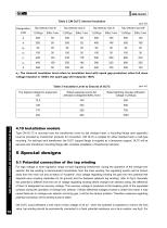
TYPE CM OIL-IMMERSED ON-LOAD TAP CHANGER TECHNICAL DATA Table 2 CM OLTC internal Insulation 4.10 Installation models Type CM OLTC is mounted onto the transformer cover by tap changer head, a mounting flange (see appendix) must be provided by transformer producer for connection. CM OLTC is suitable for either standard tank or bell-type mounting. For bell-type tank transformer, the OLTC support flange is supplied as a temporary support, OLTC will be secured onto transformer mounting flange after complete installation of transformer bell-tank. 5 Special designs 5.1 Potential connection of the tap...
Open the catalog to page 11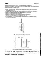
mounting location and dimensions of CM OLTC tie-in resistors, please refer to appendix 9.16 For calculating the change-over selector stress and dimensioning the tie-in resistors, the following details of the transformer specifications required when ordering: a) Complete transformer parameter: rated capacity, rated voltage, voltage regulating range, winding connection model, insulation level and so on b) Arrangement of the windings, i.e. the relative position of the tap winding to the adjacent coil or winding parts c) Operating A.C.voltage across windings or layers of windings adjacent to the...
Open the catalog to page 12All HUAMING POWER EQUIPMENT CO., LTD. catalogs and technical brochures
 TYPE WDG/WLG/WSG
39 Pages
 SHZV
SHZV100 Pages
 WSL, WDL
49 Pages
 HWV
HWV34 Pages
 CM2
CM270 Pages
 CV2
CV230 Pages
 CZ
CZ24 Pages
 CVT
CVT10 Pages
 TYPE CV & SV
34 Pages
 CMD
CMD59 Pages