CVT

CVT
1 / 10 PagesView full catalog

CVT

Product catalog summary
General Overview: The CVT vacuum on-load tap changer (CVT OLTC) is designed for dry type transformers with a voltage capacity of up to 12kV and a maximum rated through current of 160A. It features a diverter switch and tap selector, allowing for reliable performance and long life expectancy. The device supports linear regulation across 9 operation positions and can be used in Delta or Star connection configurations. It includes an HMJK-10Z automatic voltage regulator for both manual and automatic operations.
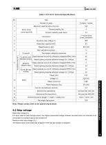
Technical Specifications: The CVT OLTC adheres to IEC60214-1:2003 standards. Key specifications include a maximum rated through current of 160A, a short-circuit current test with thermal stability at 3kA for 3 seconds, and dynamic stability at a peak value of 7.5kA. The maximum step voltage is 500V, with a rated step capacity of 80kVA. The device operates at frequencies of 50 or 60Hz and supports up to 9 operation positions. Insulation levels are specified for various conditions, including a rated separate source AC withstand voltage of 35kV and a rated lightning impulse withstand voltage of 85kV.
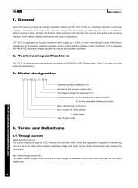
Model Designation: The model designation CVT Ⅲ -160 □ / 12 - 09 09 indicates the operation positions, tap selector contact pitch, highest voltage for equipment, connection mode (Y for star, D for any winding), maximum rated through current, and number of phases (III for three-phase, I for single-phase).
Terms and Definitions: Definitions are provided for through current, step voltage, and step capacity. The rated step capacity is the product of step voltage and load current, defining the maximum permissible capacity under continuous conditions.
Operation Conditions: The CVT OLTC should be installed indoors with ambient temperatures ranging from -25℃ to 40℃ and humidity not exceeding 95% at 25℃. The installation site should be free from gases, steam, or chemical dust that could affect insulation, and there should be no explosive gases or serious vibrations.
Installation Instructions: The CVT OLTC is mounted using four M12 screws. Connection leads should be of appropriate length to avoid stress on the tap changer, and sufficient insulation distance must be maintained. Post-installation, a complete cycle operation without load is recommended, followed by DC resistance measurement and transformer ratio testing.
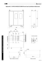
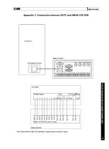
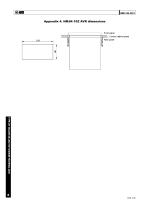
Appendices: The document includes diagrams and dimensions for the CVT OLTC connection principle, overall and installation dimensions, connection with HMJK-10Z AVR, and HMJK-10Z AVR dimensions.
See more

Catalog excerpts

CVT-1

TECHNICAL DATA TYPE CVT VACUUM ON-LOAD TAP CHANGER FOR DRY TYPE TRANSFORMER HM0.154.001 SHANGHAI HUAMING POWER EQUIPMENT CO., LTD.

 Open the catalog to page 1
CVT-3

1. General Type CVT vacuum on-load tap changer (hereafter refer as CVT or CVT OLTC) is a combined structure on-load tap changer, It comprises of diverter switch and tap selector. The tap selector changes tap from one to the adjacent without carrying current, and then the diverter switch switches under the load, the vacuum interrupters work as arcing contacts, which enables reliable performance and long life expectancy. CVT OLTC is applicable to dry type transformer with voltage up to 12kV, the max. rated through current 160A, linear regulation up to 9 operation positions, regulation at any winding...

 Open the catalog to page 3
CVT-4

Table 1 CVT OLTC Technical Specifications Note: Please contact with us for special requirement. 4.2 Step voltage Rated step voltage (U,) For each value of rated through-current, the highest permissible voltage between terminals which are intended to be connected to successive taps of the transformer. Maximum rated step voltage (Uim) The highest value of the rated step voltage for which the tap-changer is designed. TYPE CVT VACUUM ON-LOAD TAP CHANGER TECHNICAL DATA

 Open the catalog to page 4
CVT-5

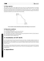
4.3 Step capacity Step capacity is the product of step voltage and load current, that is Ps=UI. Rated step capacity is the maximum permissible step capacity for the tap changer under continuous working condition, that is P stN=Ium×Ui. For a certain range of load, its rated step capacity can be represented by the range curve shown in Fig. 1. This range is defined by the maximum rated through-current on the horizontal axis and maximum permissible step voltage on the vertical axis. Loads within the defined curve is the rated values of the tap changer. Fig1 Correlation between Rated Step Capacity,...

 Open the catalog to page 5
CVT-6

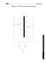
Appendix 1. CVT OLTC connection principle diagram TYPE CVT VACUUM ON-LOAD TAP CHANGER TECHNICAL DATA

 Open the catalog to page 6
CVT-7

Appendix 2. CVTIII-160Y(D)/12-0909 Overall and installation dimensions TYPE CVT VACUUM ON-LOAD TAP CHANGER TECHNICAL DATA

 Open the catalog to page 7
CVT-8

Appendix 3. Connection between OLTC and HMJK-10Z AVR TYPE CVT VACUUM ON-LOAD TAP CHANGER TECHNICAL DATA

 Open the catalog to page 8
CVT-9

TYPE CVT VACUUM ON-LOAD TAP CHANGER TECHNICAL DATA

 Open the catalog to page 9

CVT-10

TYPE VCM OIL-IMMERSED ON-LOAD TAP CHANGER TECHNICAL DATA SHANGHAI HUAMING POWER EQUIPMENT CO., LTD.

 Open the catalog to page 10

All HUAMING POWER EQUIPMENT CO., LTD. catalogs and technical brochures

  1. SHZV

    100  Pages

  2. WSL, WDL

    49  Pages

  3. HWV

    34  Pages

  4. CM2

    70  Pages

  5. CV2

    30  Pages

  6. CZ

    24  Pages

  7. TYPE CV & SV

    34  Pages

  8. CMD

    59  Pages

  9. TYPE CM

    83  Pages

*Prices are pre-tax. They exclude delivery charges and customs duties and do not include additional charges for installation or activation options. Prices are indicative only and may vary by country, with changes to the cost of raw materials and exchange rates.