
- Catalogs
- Howdon Torque limiters
- DB4603 GMR-S and GMR40-S Disc Brake Caliper - Spring Applied, Air Released


DB4603 GMR-S and GMR40-S Disc Brake Caliper - Spring Applied, Air Released

DB4603 GMR-S and GMR40-S Disc Brake Caliper - Spring Applied, Air Released
Overview
This document provides comprehensive technical information on the GMR-S and GMR40-S Disc Brake Calipers, which are spring applied and air released. These calipers are intended for industrial braking applications and support a range of disc diameters.
Specifications and Performance
- Supported disc diameters range from 610 mm to 1830 mm.
- Braking torque depends on disc diameter and air pressure, with maximum braking forces up to 36 kN.
- Minimum air pressure for full brake retraction varies between 4.8 and 8.4 bar depending on the model; maximum pressure is 9 bar.
- Braking torque formula: Torque (Nm) = Braking Force (N) × (Disc Radius - 0.06 m).
- Thruster type S has a maximum displacement volume of 1.3 liters.
- Calipers are available in right-hand or left-hand configurations and can be customized with marinisation or nodular cast iron on request.
Parts and Components
The caliper and thruster assembly includes front and rear caps, thrust collar, pushrod, seals, springs, bolts, and O-rings. A detailed parts list with part numbers and quantities supports maintenance and replacement.
Installation Guidelines
- Mount caliper on a rigid support capable of withstanding up to 36 kN braking force.
- Ensure symmetrical positioning relative to the disc.
- Use three M16 grade 8.8 bolts tightened to 150 Nm torque for secure fixing.
- For inclined mounting, use an adjustable stop screw and bias springs (kit Part No. 6700458).
- Install thruster separately with air inlet uppermost; air connection is G 1/2 BSP.
- Use flexible tubing for air supply and consider a quick exhaust valve for rapid brake response.
- Control via a 3-port, 2-position valve with open exhaust; compatible with electrical, pneumatic, or hydraulic controllers.
- Air supply must be dry and oil-free; thruster requires approximately 1.3 liters of compressed air per full stroke.
Operation Procedures
- Brake is spring applied and pneumatically released; air pressure controls braking torque.
- Retraction screw (M16 x 130) is for emergency release and maintenance safety; it must be removed during normal operation and replaced with a red plastic cap.
- Maintain thruster stroke at about 20 mm by adjusting the pushrod when brake is off.
- Monitor pad wear by measuring the gap between pad pressure plates and caliper frame; maximum allowable wear is 10 mm.
Maintenance Instructions
- Keep brake pads and discs free from oil and grease; replace contaminated pads.
- Replace pads from the rear without releasing spring clips; use part number 7080080 for new pads.
- Regularly lubricate caliper arm surfaces, knuckle joints, and pivot pins with recommended greases.
- Service or replace pivot pins after approximately one million operations or three years.
- Thruster maintenance includes cleaning pushrod, draining water, and inspecting seals and bushes.
- Seal replacements (diaphragm, rod seal, wiper seal) can be done without decompressing the spring pack; other repairs require decompression and authorized personnel.
- Never decompress springs by unscrewing the retraction screw.
- Thruster servicing involves disassembly, inspection, seal replacement, lubrication, reassembly, and leak testing.
- Pushrod removal requires thruster removal and lubrication of bearing surfaces and threads.
Recommended Lubricants
- Caliper: Medium grease with molybdenum disulphide (e.g., Castrol LMM, Shell Alvania 2 + MoS2).
- Thruster: Medium lithium-based grease with rust inhibitors (e.g., Duckham’s Keenomax L2, Castrol AP 2, Shell Alvania R2).
Spare Parts and Service
- Store spare brake pads, diaphragms, and seals in a cool, dry, contamination-free environment.
- Refer to Data Sheet DB 3604 for caliper spare parts.
- Maintain spare components for air-line equipment including filters and controllers.
- Contact Twiflex Limited or authorized agents for service and inquiries.
Critical Notes and Safety
- Always remove the retraction screw before placing the brake into service and fit the red plastic cap.
- Maintain safe clearance when adjusting the pushrod to prevent injury.
- Do not decompress springs by unscrewing the retraction screw.
- Use specified torque settings for bolts and nuts during installation and assembly.
Brake Performance Specifications
Performance data is provided for braking forces of 25 kN and 19.5 kN, detailing minimum and maximum air pressures for full retraction and operation:
- At 25 kN: Minimum retraction pressure 7 bar, maximum operating pressure 9 bar.
- At 19.5 kN: Minimum retraction pressure 6 bar, maximum operating pressure 7 bar.
- Additional noted range: Minimum retraction pressure 4.8 bar, maximum operating pressure 7 bar.
Braking torque increases with both disc diameter (610 mm to 1830 mm) and air pressure (up to approximately 18-26 bar). The relationship is graphically represented, confirming proportionality.
Unit Conversions
- 1 kNm = 736.6 lbf-ft
- 1 bar = 14.5 psi
Summary of Critical Parameters
- Minimum air pressure for full brake retraction ranges from 4.8 to 7 bar depending on braking force.
- Maximum air pressure ranges from 7 to 9 bar.
- Braking torque is directly proportional to disc diameter and air pressure.
Recommendations and Best Practices
Maintain air pressure within specified limits to ensure optimal brake performance. Select disc diameter appropriate to the required braking torque, considering the proportional relationship between diameter, air pressure, and torque. Follow installation, operation, and maintenance guidelines strictly to ensure safety and longevity of the brake system.
Catalog excerpts

DB4603 GMR-S and GMR40-S Disc Brake Caliper - Spring Applied, Air Released 270 New Pads 300 Fully Worn Pads 40 To Edge of Disc 170 Mounting Hole CRS Disc Centre Line Nominal dimensions given. For specific dimensions please contact Twiflex Limited. For GMR Mk 2 caliper details see DB 3604 Note: The caliper may be assembled as drawn (right hand assembly) or with arms and thruster oppositely handed. Minimum Pressure for Full Retraction 8·4 bar Maximum Pressure 9 bar The ratings shown on the above graph are based on fully bedded and conditioned brake pads. For bedding in and conditioning procedures see Publication M1060. Braking Force is defined as the Tangential Force acting on the brake disc at the Effective Disc Radius. Braking Torque (Nm) = Braking Force (N) x Effective Disc Radius (m) where Effective Disc Radius = Actual Disc Radius- 0.06
Open the catalog to page 1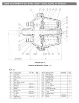
GMR-S and GMR40-S Disc Brake Caliper - Spring Applied, Air Released 27 76 Fully Retracted 156 Fully Extended Component Part No. Front Cap Rear Cap Thrust Collar Stud M16 Nut M16 Spring Washer Wiper Seal 600242 Pushrod Rod Seal 600243 Sleeve Spring Plate ‘O’ Ring 600138 ‘O’ Ring 600224 Circlip Diaphragm 7200776 Support Plate
Open the catalog to page 2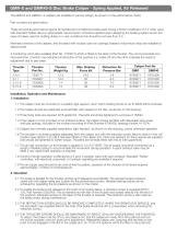
The GMR-S and GMR40--S calipers are available in various ratings, as shown on the performance charts. Part numbers are given below. These are typical performance figures for bedded and conditioned brake pads having a friction coefficient of 0.4 when used with standard Twitlex discs an appropriate ‘service factor’ should be applied when designing the braking system and in the case of brakes used for holding duties or in wet conditions this should be not less than 2.0. Marinised versions of the calipers, and thrusters with nodular cast iron castings (instead of aluminium alloy) are available to special...
Open the catalog to page 3
GMR-S and GMR40-S Disc Brake Caliper - Spring Applied, Air Released N.B. Keep fingers clear of the space between push rod and caliper arm at all times. If an inclined mounting kit is fitted, the stop screw should be re-adjusted to maintain equal pad clearance on either side of the disc. 2.5 Pad wear can be monitored by observing the gap between the lugs on the pads pressure plates and the machined surfaces on the caliper frame, when the brake is applied. Pads must be replaced {see 3.2) before the gap is reduced to zero. The maximum allowable wear on a pad is 10mm). 3. Maintenance CALIPER 3.1...
Open the catalog to page 4
GMR-S and GMR40-S Disc Brake Caliper - Spring Applied, Air Released 3.7 Leakage of air past the rod seal may be caused by damage to the seal or to the pushrod. The surface of the pushrod must be smooth and free from scoring or bruising. Note that the pushrod cannot be removed whilst the thruster is dismantled. (For removal and replacement of the push rod see 3.11 below). The rod seal (which has two parts, the P.T.F.E. sealing ring and an 0-ring) may be removed using a small screwdriver or similar tool. Take care not to damage the groove. Once removed the seal should not be re-used. When fitting...
Open the catalog to page 5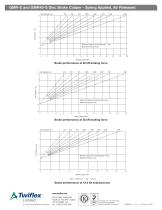
Disc Diameter mm 610 760 915 1830 GMR-S and GMR40-S Disc Brake Caliper -1065 1220 Applied, Air Released Spring 1370 1525 0 0 1 Air Pressure - bar - bar Air Pressure Air Pressure - bar 1 2 3 Minimum Pressure for Full Retraction 7 bar Maximum Pressure 9 bar Minimum Pressure for Full Retraction 7 bar Maximum Pressure 9 bar Minimum Pressure for Full Retraction 7 bar Maximum Pressure 9 bar 12 14 16 18 20 22 Brake performance at 30 kN braking force Disc Diameter mm Air Pressure - bar - bar Air Pressure Air Pressure - bar Minimum Pressure for Full Retraction 6 bar Maximum Pressure 7 bar Minimum Pressure...
Open the catalog to page 6All Howdon Torque limiters catalogs and technical brochures
 BSAB 90 DUAL-action
2 Pages
 superior braking solutions
10 Pages
 superior solutions
8 Pages
 hydraulic-power-units
22 Pages
 SOBO® iQ
1 Page
 Svendborg Brakes
112 Pages
 Layrub Couplings
2 Pages
 Industrial Disc Brakes
48 Pages
 DB 2002
2 Pages
 DB 2009
2 Pages
 DS2508
2 Pages
 DS2000 MR Disc Brake Caliper
2 Pages
 DS1500 MS Disc Brake Caliper
2 Pages
 DS1000 MU Disc Brake Caliper
2 Pages
 Brake Disc Hubs
1 Page
 Brake Discs
1 Page
 Torque Limiter Brochure
8 Pages
 Wedgegard® Phasing Hub
1 Page
 Chain Type Coupling
1 Page
 Gear Type Coupling
1 Page
 PFS Coupling
1 Page
 DFS Coupling
1 Page
 NFS Coupling
1 Page
 Type S HUB
1 Page
 Type SAE Spacer
1 Page
 Disc Hubs
1 Page
 Phasing Hubs
1 Page
 DS1508
2 Pages
 DS1507
2 Pages
 DS1003
2 Pages
 Type CFS Coupling
1 Page
 Chain & Pulley Drives
1 Page
 Type DIN Spacer
1 Page


- Flexible coupling
- Shaft shaft coupling
- Friction brake
- Pack unit
- Torque coupling
- Spring brake
- Zero-backlash shaft coupling
- Transmission coupling
- Electric hydraulic power unit
- Friction brake caliper
- Electromagnetic brake
- Compact coupling
- Motor shaft coupling
- High-torque coupling
- Pump coupling
- Hydraulic brake
- Machine shaft coupling
- Pneumatic brake caliper