- Catalogs
- Houdec Innovation
- Float operated flow switches Series 1020…
Float operated flow switches Series 1020…
1 /2Pages

Float operated flow switches Series 1020…
1 /2Pages
Catalog excerpts
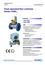
Technical Data Sheet 50466-628 July 2017 Flow Switches Float operated flow switches Series 1020… ● type 1020T ● type 1020B USE The type 1020 flow switch is designed to indicate inadequate or excess fluid flow in a horizontal pipe. It has a numerous possible applications, of which the most common are: triggering alarm systems switching on security devices, starting and stopping auxiliary devices Examples of uses flow monitoring in cooling circuits, the control of pump units, lubrication circuits PRINCIPLE A variable section float with a magnetic extension moves vertically inside a calibrated seat. Its deplacement is proportional to the rate of flow. The magnetic extension of the float acts on a mlagnet linked to an electric contact which delivers an alarm signal. The switch is set for a specified flow rate termed the “flow switching point”. DESCRIPTION This instrument consists of: ɀ A cast or mechanical welded body, inside which is the calibrated seat. The unit is connected either by tapped connectors or flanges ɀ a float fitted with a magnet extension ɀ A guide tube, on which the contact and terminal box are fixed ɀ A terminal box with gland for the electric cable
Open the catalog to page 1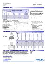
Technical Data Sheet 50466-628 July 2017 Flow Switches TECHNICAL DATA Flow rates Connector DIN Flange Normal max. flow rate Liq. d=1 1cPo Standard switching flows* Liq. d=1 1cPo Maximum Operating pressure: (up to 120°C) 16 bar for bronze model (except 2’’: 10 bar) 25 bar for the steel model. Up to 100 bar for stainless steel, depending on model. Maximum operating temperature: 80°C up to 250°C with heat screen Terminal box: Standard: light alloy IP¨54. Brass cable gland with neoprene membrane for cable from Ø8 to 11mm Explosion proof: standard II 2G EXdIICT6Gb In light alloy IP67 ATEX certified....
Open the catalog to page 2All Houdec Innovation catalogs and technical brochures
 Rotameter series 250
8 Pages


- Flowmeter
- Volume flow monitor
- Liquid flow monitor
- Gas flow monitor
- Level transmitter
- Liquid level transmitter
- Flow controller
- Liquids level gauge
- Variable-area flow meter
- Digital output level transmitter
- Liquid flow switch
- Sight glass level indicator
- Electronic level gauge
- Explosion-proof level transmitter
- Material flow switch
- Stainless steel level transmitter
- Storage tank level indicator
- HART level transmitter
- Air flow monitor