
- Catalogs
- Horner Automation Group
- HE-TK001

HE-TK001
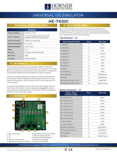
HE-TK001
Catalog excerpts
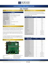
HORNER AUTOMATION GROUP 1 TECHNICAL SPECIFICATIONS GENERAL 6. Adjustment Knob for RTD Input 7. LEDs for Digital Outputs 8. Switches for Digital Inputs 9. Fuse and Fuse Holder The Universal I/O Simulator is provided with a 24VDC 1-Amp Power Supply (Power Brick). A removable AC power cord connects to the Power Brick on one side and to a wall outlet on the other. 24VDC is supplied via a permanently attached cord terminated with a barrel connector. The barrel connector plugs directly into the Universal I/O Simulator to provide power. 24VDC is passed through the board and to the V+ and Common connections in order to power the OCS and to supply any I/O power required. If connected and powered correctly, the Power LED Indicator will be lit. If the Power LED Indicator is not lit, please check to see if the fuse is connected and installed correctly. If it is, and the Power LED Indicator is still not lit, check your power supply. 3 OVERVIEW 1. Power Connector Refer to the datasheet of the OCS controller being used. Match the following wires to OCS Power and I/O terminal connections. Depending on the OCS model, some wires may not be used; tape them off separately from one another to avoid circuitry damage. Top Connector - J2 Input Connector Pinout Bottom Connector - J3 page 1 of 2 Output / Power Connector Pinout 59 South State Ave., Indianapolis, IN 46201 | (p) 317.916.4274 (tf) 877.665.5666 (f) 317.639.4279 | www.hornerautomation.com Please visit our website for a complete listing and to learn more about certified Horner Automation products. This document is the property of Horner Automation Group, and is subject to change.
Open the catalog to page 1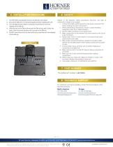
1. The HE-TK001 conveniently mounts on a DIN rail [*see below]. 2. Be sure the DIN rail is in a horizontal position before installing the unit. 3. The orientation shown below is necessary to prevent the unit from slipping off the DIN rail. 4. Align the unit on the DIN rail then push the DIN rail clip until it clicks into place. Check to ensure that the unit is secure on the DIN rail. 5. Do NOT mount the unit on its side as this may cause the unit from slipping off the DIN rail. Adhere to the following safety precautions whenever any type of connection is made to the module: 1. Connect the safety...
Open the catalog to page 2All Horner Automation Group catalogs and technical brochures
 RCC6512
2 Pages
 I/O Simulator
1 Page
 SmartStix I/O
2 Pages
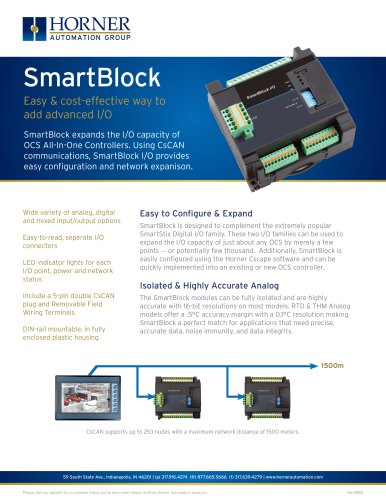 SmartBlock
2 Pages
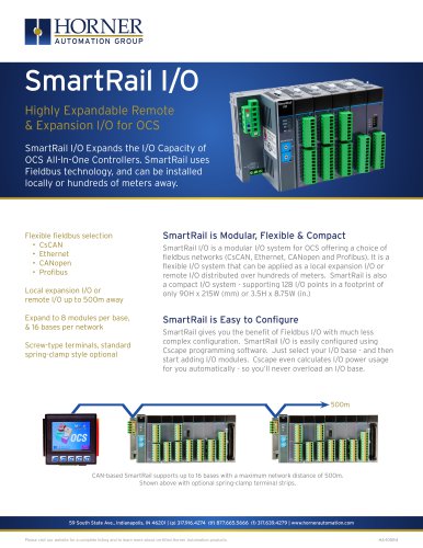 SmartRail I/O
2 Pages
 OCS-I/O
7 Pages
 CANVAS COLLECTION
7 Pages
 Modular Controllers
2 Pages
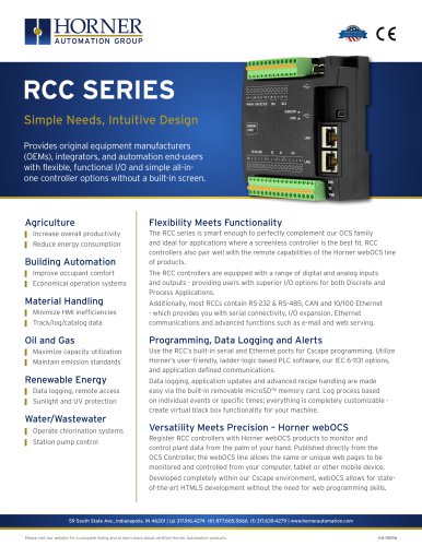 RCC SERIES
2 Pages


- Automation software solution
- Digital I/O
- IO module
- Analog I/O
- Digital IO module
- Industrial software
- Interface software
- HMI
- Fieldbus I/O module
- Programmable logic controller
- Programming software solution
- Development software
- Analog IO module
- Remote I/O
- LCD HMI
- Ethernet HMI
- Compact converter
- Remote IO module
- Ethernet programmable logic controller
- RS-232 HMI