- Catalogs
- HORIBA STEC
- Capacitance Manometer VG Series
Capacitance Manometer VG Series
1 /4Pages

Capacitance Manometer VG Series
1 /4Pages
Catalog excerpts

Product Introduction Development of Capacitance Diaphragm Gauge Development of Capacitance Diaphragm Gauge Sotaro KISHIDA In the deposition process or an etching process that made to be used for the fabrication of LEDs, semiconductors, FPDs and solar cells, various gases are used and the process pressure gives large effect on product quality, so the excellent corrosion resistance, and without gas dependent, and high accuracy are required to vacuum gauge . To provide solutions to these requests, HORIBA STEC has developed the Capacitance Diaphragm Gauge “VG-200 Series”, and the results of the performance evaluation were superior reproducibility and long term stability. Here, we describe the product features and performance evaluation results of the VG-200. Introduction Recently, it is becoming very important to measure and control pressure in the manufacturing processes for maintaining and control product quality in all kinds of industries. For example, in the manufacture of semiconductors, there is a process that requires control of small changes in pressure in a low-vacuum region, and vacuum meters are required to be able to measure a small pressure change with high precision. In addition, product manufacturing processes utilizing vacuum are sometimes used in the renewable energy, display, and MEMS industries. Therefore, vacuum meters are used in a wide range of industries as described above. From this, it is apparent that vacuum instrumentation with precision and stability will be more important in the future. To meet such requirements of the marketplace, we independently developed a sensor structure and signal-processing algorithm. In addition, we succeeded in the development of self-temperature-regulating, small-sized, and high-precision VG-200 series of capacitance manometers through the development of a manufacturing technology for precision welding in house as introduced below. Measurement principle of capacitance manometer The measurement principle of capacitance manometer is as follows (Figure 1): The sensor body is divided into standard chamber and English Edition No.47 April 2017 Fixed electrode Control room Measurement room Pressure to be measured Diaphragm Getter Figure 1 Diagram of Capacitance Diaphragm Gauge measurement chamber by a diaphragm. The standard chamber, which is equipped with a fixed electrode, is maintained in the vacuum state by a getter material*1. On the other hand, in the measurement chamber, if a distance between the electrode and the diaphragm changes because of a deflection of the diaphragm caused by a change in pressure, the capacitance generated between them also changes. Measuring the change in capacitance and converting it into a pressure value determines the pressure value in the measurement chamber. In addition, since the force (pressure) applied to the diaphragm can be directly converted into an output, the product performance is not dependent on the type of gas, and it is possible to measure pressure with high precision. *1: Getter material: A material that absorbs excessive gas to maintain a va
Open the catalog to page 1
HORIBA Technical Reports Features of VG-200 series capacitance manometers Product specifications Figure 2 and Table 1 show the external appearance and specifications of VG-200 series products, respectively. Sensor structure The sensor structure of VG-200 series capacitance manometers is as follows (Figure 3): The electrode is fixed to the sensor body in a way that a constant force is applied to the entire electrode in the same direction on a consistent basis without being jointed to the sensor body directly. Using this electrode structure that we independently developed allowed us to minimize the...
Open the catalog to page 2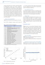
roduct Introduction Development of Capacitance Diaphragm Gauge causing measurement error. We have solved this problem by implementing a unique circuit, which is designed to use a sampling circuit whose phase is synchronized with the output pulse from a sensor to detect a pulse amplitude always in the same phase. This circuit lowers the factors for measurement error and reduces the effects of disturbances that occur during analog computing that achieved higher resolution. In addition, we changed the structure of this circuit based on the premise of eliminating inverting and non-inverting electric...
Open the catalog to page 3
HORIBA Technical Reports HORIBA Technical Reports Pressurization (times) Figure 7 Test result of proof pressure times, and Figure 7 shows the output stability when an excessive pressure (350 kPa [abs]) is continuously applied for an hour. With the use of a metal diaphragm with superior mechanical properties, it was confirmed that the output shift could be minimized even when an excessive pressure was applied to the sensor and was very small even when the sensor was exposed to the atmosphere repeatedly. Conclusion We succeeded in the development of a small-sized, high-precision, and corrosion-resistant...
Open the catalog to page 4All HORIBA STEC catalogs and technical brochures
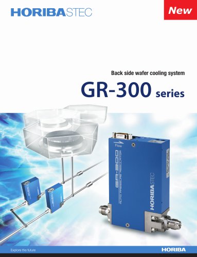
 GR-300 Series
1 Page
 1000M Series
2 Pages
 ru1000
4 Pages
 HF HD-960L
5 Pages
 CVS-ONE Brochure
4 Pages
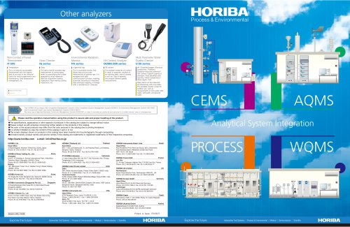
 CEMS
CEMS4 Pages
 Cathodoluminescence H-CLUE
5 Pages
 Cathodoluminescence F-CLUE
5 Pages
 HE-960HC
5 Pages
 CAMSIZER X2 Brochure
12 Pages
 CAMSIZER P4 Brochure
12 Pages
 Brochure-TPNA-500
6 Pages
 AP-370 Series Brochure
12 Pages
 OMNI TERS Probes
2 Pages
 NanoRaman Brochure
7 Pages
 51 series Brochure
6 Pages
 VULCAN Evo
4 Pages
 MEDAS
MEDAS8 Pages
 OBS-ONE GS
6 Pages
 MEXA-ONE Brochure
26 Pages
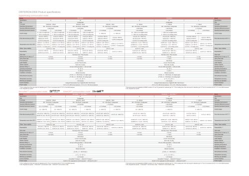
 CRITERION D507 Series
3 Pages
 Mass flow Controller & Meter
2 Pages
 Oil analysis
3 Pages
 Back number of CSR Reports
13 Pages
 HORIBA Report
86 Pages
 Soap Film Flow Meter
1 Page
 MI/MV
MI/MV1 Page
 LV-F series
1 Page
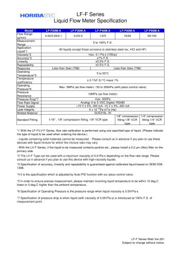 LF-F series
1 Page
 Criterion, D200 series
16 Pages
 Pressure Controller
8 Pages
 SEC-Z500MGX
16 Pages
 Fluid Controle Equipment
4 Pages
 Rasidual Gas Analizer
6 Pages
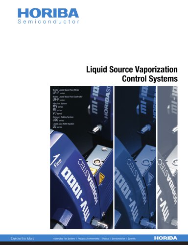 Vaporizers
8 Pages


- BIO-UV flow meter
- Liquid flow monitor
- BIO-UV measuring instrument
- BIO-UV gas analyzer
- BIO-UV monitoring analyzer
- BIO-UV liquids analyzer
- BIO-UV measuring system
- Pressure gauge
- Pressure limiter
- BIO-UV gas flow meter
- Single-stage pressure regulator
- Industrial pressure limiter
- Analog pressure gauge
- Precision flow meter
- In-line flow meter
- BIO-UV inspection system
- Compact flow monitor
- DC flow monitor
- RS485 flow monitor
- BIO-UV mass flow meter