- Catalogs
- Honeywell Video Systems
- S4 Mains Powered Interface
S4 Mains Powered Interface
1 /28Pages
S4 Mains Powered Interface
1 /28Pages
Catalog excerpts
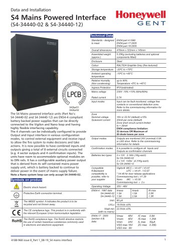
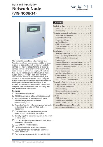
The S4 Mains powered interface units (Part No's: S4-34440-02 and S4-34440-12) are EN54-4 compliant battery backed power supplies that can be directly connected to the Vigilon and Nano loop and having highly flexible interfacing capability. The 4 channels can be individually configured to provide Output and Input interface in various configuration modes, to control external equipment and receive input to allow the fire system to make decisions and take actions. It is now possible to have combined inputs and outputs giving a total of 8 external circuits connected (e.g. 4 sector outputs and 4 confirmation inputs). The units have room to accommodate optional modules on to DIN rails. It has a configurable auxiliary power output that is derived from its self contained mains power supply unit, which is battery backed to continue to deliver power in the event of mains supply failure. Note a Nano system loop can only accept S4-34440-02.
Open the catalog to page 1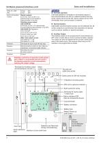
S4 Mains powered interface unit Features Vmax Vmin Sector and Auxiliary Outputs Sector outputs: 0.5A max. each at 24V ± 3V, electronically current limited to approximately 1A at 25ºC Auxiliary power output: (S4-34440-02) 0.5A max. at 24V ± 3V, electronically current limited to approximately 1A at 25ºC (S4-34440-12) Regulation: 0 to 0.5A with 12V ±0.5V or 24V ±0.5V 0.5A to 0.65A max. with 12V ±2V or 24V ±2V Max. total output current: S4-34440-02 = 1.5A S4-34440-12 = 2.5A Terminals for spur circuit off main loop BS EN 61000-6-3:2007 A1:2011 EMC for residential, commercial & light Industry. Fail-safe...
Open the catalog to page 2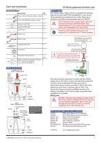
Data and Installation S4 Mains powered interface unit Data and Installation S4 Mains powered interface unit Softskin (Fire Tuf) CABLE TERMINATION DO NOT undertake high voltage insulation tests WITH THE CABLES CONNECTED to the Interface unit and external equipment. Such a test may damage the electronics circuitry in external equipment and in the Interface unit. Cable termination! EARTH DRAIN WIRE Should not be more than 50mm long and must be sleeved The mains supply cable must be a standard fire resisting type and should meet PH30 classification, such as any of the standard and enhanced loop cable....
Open the catalog to page 3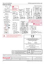
Data and Installation S4 Mains powered interface unit External wiring LOOP IN Output Connections LOOP ' COMMON Auxiliary Output: End-of-line units Must be fitted inside the last device yellow, violet, brown It is possible to connect a number of LEDs in series (current is 1.5mA). Sector Output Sector Output with Inductive load (eg Relay) Input Connections Zone Input To avoid damage to equipment always configure the interface inputs and outputs before connecting the external circuits. Switch Input Normally closed contacts should be used for fail-safe applications. Connected to metal enclosure The...
Open the catalog to page 4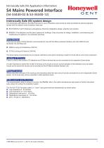
Intrinsically Safe (IS) Application Information The intrinsically safe detection and alarm devices for use in hazardous area should be wired and tested by trained engineers familiar with the relavent code of practice, these are: □ BS EN 60079-14:2014 Explosive atmospheres. Electrical installations design, selection and erection □ BS5839-1 Fire detection and fire alarm systems for buildings. Code of practice for design, installation, commissioning and maintenance of systems in non-domestic premises Zener Barriers! There are two types of Zener Barriers recommended for use with the Mains powered...
Open the catalog to page 5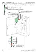
S4 Mains powered interface unit How to fit a Zener Barrier on to the DIN rail in a Mains Powered Interface Ensure the DIN Rail is able to accomodate Zener Barriers. Carefully insert a terminal screwdriver to open out DIN rail fitment on the Zener Barrier. See markings on the Zener Barrier enclosure to identify exactly where the screwdriver is to be inserted. Position the Zener Barrier with screwdriver engaged to the left of the start of the DIN rail. Slide the Zener Barrier on to the DIN Rail to the right to a desired position. Remove the screwdriver and ensure the Zener barrier is secured to...
Open the catalog to page 6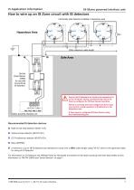
IS Application Information S4 Mains powered interface unit IS Application Information S4 Mains powered interface unit 200m maximum cable length 764744 Zener Barrier (Z969) for use with conventional IS detectors Mains powered interface unit Ensure the IS Detectors are wired to the respective Z+ and Z- terminals. During commissioning ensure the Zone is configured for IS Esser Sensor operation. Failure to correctly wire and configure the Zone input may result in unsafe operation of IS detectors in the Hazardous area. A Zone input is configured IS Esser Sensor using the Commissioning tool. Recommended...
Open the catalog to page 7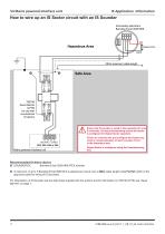
S4 Mains powered interface unit IS Application Information Hazardous Area 200m maximum cable length Safe Area 765746 Zener Barrier (Z779) for use with conventional IS alarms Ensure the IS sounder is wired to the respective S+ and S- terminals. During commissioning ensure the Sector is configured for Output Sector operation. Failure to correctly wire and configure the Output may result in unsafe operation of alarm sounder circuit in the Hazardous area. Mains powered interface unit Output Sector is configured using the Commissioning tool. Recommended IS Alarm device □ SOUNDER-EX Banshee Excel IS28...
Open the catalog to page 8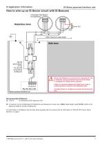
S4 Mains powered interface unit How to wire up an IS Sector circuit with IS Beacons Intrinsically Safe Beacon IS FlashDome Hazardous Area 200m maximum cable length Safe Area 764746 Zener Barrier (Z779) for use with conventional IS Beacons Ensure the IS Beacons are wired to the respective S+ and S- terminals. During commissioning ensure the Sector is configured for Output Sector operation. Failure to correctly configure the Output may result in unsafe operation of alarms in the Hazardous area. PB2, PB3, PB4 or PB5 Mains powered interface unit An Output Sector is configured using the Commissioning...
Open the catalog to page 9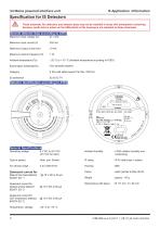
S4 Mains powered interface unit Specification for IS Detectors These automatic fire detectors and detector base may not be installed in areas with atmosphere containing bensene, acetic acid or esters as the ABS plastic of the housing is not resistant to these chemicals. General detector data according to ATEX Maximum Input voltage (Ui) Maximum Input current (Ii) Maximum Output current (Io) Maximum internal Capacity (Ci) : - 20 °C to + 70 °C (Ambient temperature according to ATEX) : II 2G (with safety barrier Part No. 764744) Detector identification according to ATEX General Specifications Operating...
Open the catalog to page 10All Honeywell Video Systems catalogs and technical brochures
 Network Node (VIG-NODE-24)
16 Pages
 Copper Network Card (EN)
2 Pages
Archived catalogs
 Honeywell Systems 2011-2012 Catalog
188 Pages
 Mobile
16 Pages
 Digital Video Recorders
40 Pages
 Intelligent Analytics Solutions
12 Pages
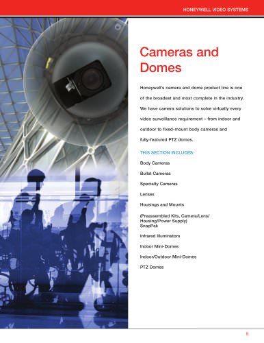 Cameras and Domes
64 Pages
 Systems and System Accessories
14 Pages
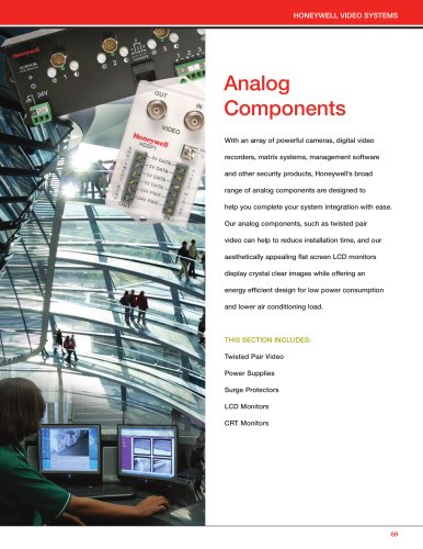 Analog components
22 Pages

- Digital imager
- Visible imager
- Management software solution
- Automation software solution
- CMOS camera module
- Industrial camera module
- Infrared imager
- Monitoring camera system
- Full-color camera system
- Windows software
- Real-time software
- Cloud-based software
- Control software
- Detection camera system
- Image processing camera module
- Monitoring software solution
- Monochrome camera module
- Communication gateway
- Waterproof camera module
- HD camera module