- Catalogs
- Honeywell Video Systems
- Network Node (VIG-NODE-24)
Network Node (VIG-NODE-24)
1 /16Pages

Network Node (VIG-NODE-24)
1 /16Pages
Catalog excerpts

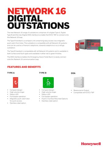
The Vigilon Network Node (also referred to as Terminal node) can accommodate additional cards in place of loop cards, such as network cards to connect two networks together and IO cards to connect remote printer and Central system. The node houses its own power supply with batteries that provide standby power in the event of mains supply failure. A lockable front door prevents unauthorised access to fire alarm controls, but allows all of the indicators to be seen. Two push button controls are located on the front door below the display that enable Fire messages to be scrolled in the event of multiple fires. The node is designed for surface or semi flush mounting, with rear and top cable entry points. Features □ Two master alarm circuits □ RS485 to connect to a Repeat Indicator panel □ RS232 to connect to another control panel (domain bridge) external printer or commissioning tool □ Two sets of auxiliary relay change over contacts configurable to operate with fire, fault or disablement □ One set of clean voltage-free change over contacts that operates with fire events □ Standby supply to power the system in the event of mains failure □ LCD alphanumeric type display with back light to show event information □ LED lights for event indication □ Local audible buzzer to announce events □ Push button for essential controls and menu driven commands □ Four programmable control buttons (U1 to U4) Technical data- - -- -- -- -- -- -- 2 Panel- -------------------- 2 Notes on system installation - -- -- -- 3 Installation requirements - -- -- -- -- -- 3 Cable type and routing ------------ 4 Earth continuity - -- -- -- -- -- -- -- 4 Mains supply -----------------4 Installation - -- -- -- -- -- -- -- 4 Back box installation - -- -- -- -- -- -- 5 Semi-Flush fixing the Network Node ----- 6 Cable termination and markings - -- -- -- -6 Mains supply ----------------- 7 Mains and battery supply connections ----- 7 Mains and battery supply connections ----- 7 Terminals for external circuits - - -- -- -- -8 Network connections - -- -- -- -- -- -- 9 Master alarm circuits - -- -- -- -- -- -- 9 Auxiliary relay circuits - -- -- -- -- -- -9 Clean contacts - -- -- -- -- -- -- -- - 10 Remote printer - -- -- -- -- -- -- -- - 10 RS232 / RS485 Communication - - -- -- -- 10 Network of single systems - -- -- -- - 11 Copper network connections - -- -- -- -- 11 Fibre network connections - -- -- -- -- - 11 Network wiring- - -- -- -- -- -- -- -- 12 Network cable screen continuity - - -- -- -- 12 Installing with MICC Cable - - -- -- -- -- 12 Cables-----------------13 Cable separation - -- -- -- -- -- -- -- 13 Requirements of cables - -- -- -- -- -- - 13 Network cables - - -- -- -- -- -- -- -- 13 Domain Bridge across Networks ----- 15 On completion of installation - -- -- -- -- 16 4188-917 issue 2_7-14_gent net node_Network node 1
Open the catalog to page 1
Data and Installation Network node 2 4188-917 issue 2_7-14_gent net node_Network node
Open the catalog to page 2
Network node Data and Installation The power-up of the Network Node and commissioning of the system is done by the Servicing organisation. Installation requirements It is recommended that the installer follow the general requirements of BS5839:Part 1, which is the code of practice relating to fire detection and alarm systems for buildings. The installer must follow the relevant parts of BS7671 Requirements for Electrical installations, IEE wiring regulations 16th edition if installation is in the United Kingdom, UK. To prevent the possibility of damage or dirt degrading the performance or appearance...
Open the catalog to page 3
Data and Installation Network node Data and Installation Network node Mains supply It is the installer's responsibility to provide adequate fixtures and fittings for the type of construction surface onto which a product is to be installed, whilst utilising the fixing points on the respective product. As an aid to this decision, the weight and overall size of each full assembly together with implications on cable entries and routing should be taken into consideration. Mains supply to any fire alarm control and indicating equipment must be via an unswitched 5A fused spur unit. A disconnect device...
Open the catalog to page 4
Network node Back box installation These instructions cover information on the backbox assembly only, all remaining packages are installed during the commissioning by the servicing organisation. Identify the package NETWORK-NODE-24 and check that it contains all the parts. Remove the temporary cover from the Back box. Knock out/in the required cable entry points from the Network node back box. Use the fixing points provided mount the Back box to the wall using suitable fixings. The network node can be surface or flush mounted. The fixings must support a fully assembled network node with batteries...
Open the catalog to page 5
Network node Semi-Flush fixing the Network Node Cable termination and markings The Node may be flush mounted using a flush MICC Softskin (Fire Tuf) CABLE TERMINATION surround VIG-24-FLUSH. A stainless steel variant of CABLE TERMINATION the flush surround (VIG-FLUSH-SS) will require a EARTH MICC CABLE stainless steel door VIG_DOOR_SS. DRAIN Softskin Cable GLAND WIRE a. Check the contents of the flush surround Should not ZINC PLATED be more than package. GLAND LOCK WASHER 50mm long and must be b. Cut out an aperture in the wall to allow the flush BRASS sleeved LOCKNUT surround to be fitted, see...
Open the catalog to page 6
Network node Ensure that the mains supply cable enters the panel through a dedicated cable entry point. These fire alarm system products are NOT designed to be powered from IT Power systems. All mains powered equipment must be earthed. Mains and battery supply connections The mains and battery supply cables must be installed to the stage to facilitate the power up for commissioning, which is carried out by the Servicing organisation. Where mains cable is to remain disconnected, its tail ends must be insulated to prevent dangerous conditions arising in the event of accidental switching On of the...
Open the catalog to page 7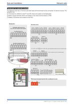
Data and Installation Network node The Network node has a Terminal card that holds all the terminals for the connection of external circuits. The exception are: □ Terminals for CARDS in slots P7 and P8, these are located on the Backplane □ Mains supply terminals which are located on the mains terminal block on PSU □ Battery connections are located on the PSU. Terminal card NETWORK CARD IN SLOT P8 0V1 +VE1 -VE1 0V2 N/C +VE2 -VE2 N/C PSU board (located behind the cardboard cover) L N
Open the catalog to page 8All Honeywell Video Systems catalogs and technical brochures
 Copper Network Card (EN)
2 Pages
 S4 Mains Powered Interface
28 Pages

Archived catalogs
 Honeywell Systems 2011-2012 Catalog
188 Pages
 Mobile
16 Pages
 Digital Video Recorders
40 Pages
 Intelligent Analytics Solutions
12 Pages
 Cameras and Domes
64 Pages
 Systems and System Accessories
14 Pages
 Analog components
22 Pages

- Digital imager
- Visible imager
- Management software solution
- Automation software solution
- CMOS camera module
- Industrial camera module
- Infrared imager
- Monitoring camera system
- Windows software
- Full-color camera system
- Real-time software
- Cloud-based software
- Control software
- Detection camera system
- Image processing camera module
- Monitoring software solution
- Monochrome camera module
- Communication gateway
- Waterproof camera module
- HD camera module