
- Catalogs
- Honeywell Thermal Solutions
- IFD 450, IFD 454


- Company
- Products
- Catalogs
- News & Trends
- Exhibitions
IFD 450, IFD 454

IFD 450, IFD 454
The document provides technical details on the IFD 450 and IFD 454 automatic burner control units, designed for continuous operation with industrial burners. These units support both modulating and stage-controlled burners and feature continuous self-testing for faults, utilizing UV or ionization sensors for flame control.
The IFD 450 and IFD 454 are EC type-tested and certified under directives such as the Gas Appliances Directive, Low Voltage Directive, and Electromagnetic Compatibility Directive. They are also approved for use in Russia.
These units ignite and monitor gas burners, reacting swiftly to process needs. The IFD 450 locks out immediately upon flame failure, while the IFD 454 allows for automatic restart. Program status and flame signal levels are directly readable from the unit.
Examples include two-stage-controlled and modulating-controlled burners with UV control, illustrating burner management from start-up to normal operation.
Diagrams are provided for various control configurations, including ionization and UV control.
The document details the program sequence for normal start-up, start-up without flame signal, and flame failure behavior, including safety times and actions during flame failure.
Guidance is offered on cable selection, solenoid valve installation, and flame control using different sensors, along with emergency stop procedures and wiring considerations.
Technical specifications include operating controls, installation instructions, and details on mains voltage, safety times, and permissible sensors.
Maintenance cycles and available accessories, such as high-voltage cables and μ-ammeters, are listed.
Operational procedures and fault handling are outlined, including start-up processes and safety times for fault lock-out and restart attempts.
A 2-digit 7-segment display indicates program status and fault messages, with a table for interpreting key fault codes.
The IFD 450 locks out immediately upon flame failure, while the IFD 454 attempts a restart, complying with EN 746-2 for safe restart conditions.
Normal shutdown involves closing valves and checking for extraneous signals, with fault lock-out if flame simulation issues are unresolved within the delay time.
Guidelines for cable selection and proper grounding and wiring are provided to prevent equipment damage.
Recommendations for emergency stop procedures and solenoid valve installation are included, ensuring alignment with specific applications.
The units are interchangeable with previous models, with a selection table guiding the choice based on safety time requirements and mains voltage.
Flame detection systems using ionization and UV sensors are described, with compliance to EN 746-2 standards necessary.
Flame signals can be displayed using an external μ-ammeter, with care to prevent incorrect signals.
Accessories include high-voltage cables, interference-suppressed electrode adapters, and a DC micro-ammeter.
Detailed specifications for the IFD 450 and IFD 454 models are provided, including installation requirements.
The units feature a 2-digit 7-segment display and a reset/information button, with installation instructions ensuring IP 54 enclosure.
Minimal maintenance is required, with a glossary explaining key terms.
Feedback on the document is invited, with contact details for Elster GmbH provided for further inquiries.
Catalog excerpts
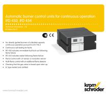
Automatic burner control units for continuous operation IFD 450, IFD 454 Technical Information · GB 6 Edition 06.12 • For directly ignited burners of unlimited capacity continuous operation pursuant to EN 746-2 • Continuous self-testing for faults • IFD 450 includes immediate fault lock-out following flame failure • IFD 454 includes restart following flame failure • Flame control with UV sensor or ionization sensor • Multi-flame control with an additional flame detector • Checking that the gas valve is closed upon start-up • EC type-tested and certified
Open the catalog to page 1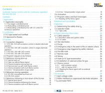
Contents Automatic burner control units for continuous operation IFD 450, IFD 454 . . . . . . . . . . . . . . . . . . . . . . . . . . . . . . . . . . 1 Contents . . . . . . . . . . . . . . . . . . . . . . . . . . . . . . . . . . . . . . . . 2 1 Application . . . . . . . . . . . . . . . . . . . . . . . . . . . . . . . . . . . . 4 1.1 Application examples . . . . . . . . . . . . . . . . . . . . . . . . . . . 6 1.1.1 Two-stage-controlled burner . . . . . . . . . . . . . . . . . . . . . . . . . 6 1.1.2 Modulating-controlled burner . . . . . . . . . . . . . . . . . . . . . . . . 7 1.1.3 Modulating-controlled...
Open the catalog to page 2
Contents 8 Technical data . . . . . . . . . . . . . . . . . . . . . . . . . . . . . . . . 29 8.1 Operating controls . . . . . . . . . . . . . . . . . . . . . . . . . . . . 30 8.2 Installation . . . . . . . . . . . . . . . . . . . . . . . . . . . . . . . . . . 30 9 Maintenance cycles . . . . . . . . . . . . . . . . . . . . . . . . . . . . . 31 10 Legend . . . . . . . . . . . . . . . . . . . . . . . . . . . . . . . . . . . . . . 31 11 Glossary . . . . . . . . . . . . . . . . . . . . . . . . . . . . . . . . . . . . . 32 11.1 Waiting time tW . . . . . . . . . . . . . . . . . . . . . . . . . . . ....
Open the catalog to page 3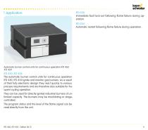
IFD 450 Immediate fault lock-out following flame failure during operation. IFD 454 Automatic restart following flame failure during operation. Automatic burner control units for continuous operation IFD 450, IFD 454 IFD 450, IFD 454 The automatic burner control units for continuous operation IFD 450, IFD 454 ignite and monitor gas burners. As a result of their fully electronic design they react quickly to various process requirements and are therefore also suitable for frequent cycling operation. They can be used for directly ignited industrial burners of unlimited capacity. The burners may be...
Open the catalog to page 4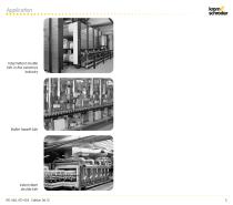
Intermittent shuttle kiln in the ceramics industry Roller hearth kiln Intermittent shuttle kiln IFD 450, IFD 454 · Edition 06.12
Open the catalog to page 5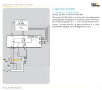
Application > Application examples 1.1 Application examples 1.1.1 Two-stage-controlled burner Control: ON/OFF or ON/HIGH/LOW/OFF The burner BIO/BIC starts at low-fire rate. Once the normal operating state is reached, the automatic burner control unit for continuous operation IFD 454 or IFD 450 will release control. The PLC can now pulse the air solenoid valve VR..R in order to control the capacity between high and low fire.
Open the catalog to page 6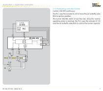
Application > Application examples 1.1.2 Modulating-controlled burner Control: ON/OFF/continuous The PLC uses the actuator IC 20 to move the air butterfly valve BVA to ignition position. The burner BIO/BIC starts at low-fire rate. Once the normal operating state is reached, the PLC uses the actuator IC 20 and the air butterfly valve BVA to control the burner capacity.
Open the catalog to page 7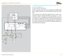
Application > Application examples 1.1.3 Modulating-controlled burner with UV control for continuous operation Control: ON/OFF/continuous The PLC uses the actuator IC 20 to move the air butterfly valve BVA to ignition position. The burner BIO/BIC starts at low-fire rate. The UV sensor for continuous operation UVD 1 is also connected in order to monitor the flame, see page 27 (... with UV sensor UVD 1). It notifies the automatic burner control unit for continuous operation IFD 454 or IFD 450 of the presence of a flame. Once the normal operating state is reached, the PLC uses the actuator IC 20...
Open the catalog to page 8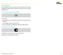
2 Certification The automatic burner control units IFD 450 and IFD 454 are designed for applications pursuant to the Machinery Directive (2006/42/EC). pursuant to – Gas Appliances Directive (90/396/EEC) in conjunction with EN 298 – Low Voltage Directive 2006/95/EC – Electromagnetic Compatibility Directive (2004/108/EC) Certified by Gosstandart pursuant to GOST-TR. Approved by Rostekhnadzor (RTN).
Open the catalog to page 9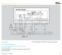
3 Function For the explanation of symbols, see page 31 (Legend). 3.1.1 IFD 450, 454 with ionization control in double- electrode operation For cable selection and wiring, see page 25 (Project plan- ning information).
Open the catalog to page 10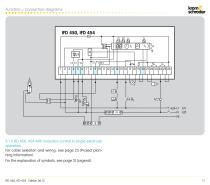
Function > Connection diagrams 3.1.2 IFD 450, 454 with ionisation control in single-electrode For cable selection and wiring, see page 25 (Project plan- ning information). For the explanation of symbols, see page 31 (Legend).
Open the catalog to page 11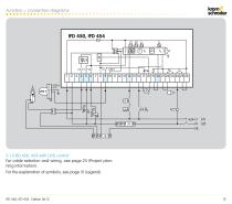
Function > Connection diagrams 3.1.3 IFD 450, 454 with UVD control For cable selection and wiring, see page 25 (Project planning information). For the explanation of symbols, see page 31 (Legend).
Open the catalog to page 12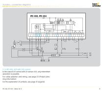
Function > Connection diagrams 3.1.4 IFD 450, 454 with UVS control In the case of UV control with UV sensor UVS, only intermittent operation is possible. For cable selection and wiring, see page 25 (Project planning information). For the explanation of symbols, see page 31 (Legend).
Open the catalog to page 13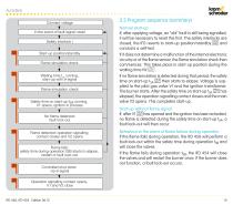
Function Connect voltage In the event of fault signal: reset Safety interlock ) 00 Start-up position/standby Flame simulation check Waiting time tW running, start-up with ϑ-signal Flame simulation check Safety time on start-up tSA running, V1 opens, ignition in process No flame detected: fault lock-out Flame detected: operation signalling contact closes and V2 opens Flame fails: safety time during operation tSB starts to elapse, restart or fault lock-out Controlled shut-down via ϑ-signal 3.2 Program sequence (summary) Normal start-up If, after applying voltage, an “old” fault is still being signalled,...
Open the catalog to page 14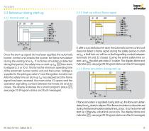
3.3 Behaviour during start-up 3.3.2 Start-up without flame signal Once the start-up signal (J) has been applied, the automatic burner control unit checks the burner for flame simulation during the waiting time tW. If no flame simulation is detected during that period, the safety time on start-up tSA 02 then starts to elapse (3, 5 or 10 s). This forms the minimum operating time of the automatic burner control unit and the burner. Voltage is supplied to the pilot gas valve V1 and the ignition transformer. After the safety time on start-up tSA has elapsed and the flame signal has been received,...
Open the catalog to page 15All Honeywell Thermal Solutions catalogs and technical brochures
 Thermal Solutions
12 Pages
 COMBUSTION CATALOG
176 Pages
 thermal IQ
4 Pages
 Magnetic relief valves VAN
4 Pages
 Tightness controls TC
12 Pages
 Pressure switches for gas DG
4 Pages
 Burners for gas BIC, BICA, ZIC
16 Pages
 Valves and butterfly valves
8 Pages
 E-SOLUTIONS FOR COMBUSTION™
4 Pages
 Field bus interface PFA 700
28 Pages
 Manual valves AKT
4 Pages
 Gas Pressure Regulator GDJ
2 Pages
 Gas Pressure Regulator VGBF
4 Pages
 Thermal equipment trip TAS
4 Pages
 Safety shut-off valve
2 Pages
 Relief valves
2 Pages
 BV.., IB..
8 Pages
 Gasfilter GFK
4 Pages
 HTS Engineered to order
8 Pages
 Training Brochure 2019
17 Pages


Archived catalogs
 HONEYWELL COMBUSTION SERVICE
4 Pages
 Burner control unit BCU 370
6 Pages
 Control valves S11T
4 Pages
 Burner control unit CM 222
4 Pages
 Gear motors GT
4 Pages
 pb_tas_akt_tas_gb 2007
6 Pages
 pb_j78r_60dj_gb
2 Pages
 Solenoid Valves for air VR
16 Pages
 Actuators IC 20, IC 40
8 Pages
 GIK
GIK2 Pages
 GIKH
GIKH2 Pages
 Product range
4 Pages


