- Products
- Catalogs
- News & Trends
- Exhibitions
Pressure Transmitter AT5020
1 /32Pages

Pressure Transmitter AT5020
1 /32Pages
Catalog excerpts

= Optional gauge pressure, absolute pressure = Convenient and user-friendly, wide options in forms and = 10-year stability of +0.2% of URL = -100kPa to 40MPa (minimum range 0 to 1kPa) = Intuitive interface and built-in buttons for quick commissioning of the device = 316L/HC/Tantalum/316L coated with PTFE/316 L gold plated/ Inconel 625 etc material = Precision in measurement = Exploration in our range of state-of-the-art pressure transmitters = Features, specification, and applications covered in detail = SIL, NACE, NEPSI, ATEX, CE PMI, EN1204 = HART 7.0/Modbus-RTU and others = Multiple standard process connections, as well as filler fluids, enabling connection to various forms of piping, connection standards are according to EN, ASME/ANSI, GB, GOST, JIS etc.
Open the catalog to page 1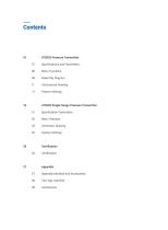
Menu Functions Assembly Diagram Dimensional Drawing Factory Settings AT5020 Single Flange Pressure Transmitter 15 Specification Parameters Menu Features Dimension Drawing Factory Settings Appendix Manifold and Accessories Two-way manifold
Open the catalog to page 2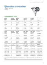
CATALOG PRESSURE TRANSMITTER AT5020 Specifications and Parameters Pressure Transmitter Range and Sensor Limits Nominal Range Maximum Range Ratio Minimum Range Lower Range Limit (LRL) Upper Range Limit (URL) Lower Range Upper Range Range Ratio Lower Range Upper Range Range Ratio Upper and lower range value setting requirements: lower range value (LRV) and upper range value (URV) are in the range of upper and lower range limits, if |URV| = |LRVI, it must be satisfied |URV| 2 minimum range, if |URV] <|LRVI, it must be satisfied |LRV| 2 Minimum
Open the catalog to page 3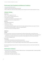
DATASHEET PRESSURE TRANSMITTER AT5020 Performance Test Standards and Reference Conditions = Test standard GB/T28474/IEC60770. = Reference condition the range is started from zero point. = Silicone oil filled, 316L stainless steel isolation diaphragm,4-20mA analog output, terminal-base fine adjusted to set value. Vibration Testing Vibration Test = 5Hz
Open the catalog to page 4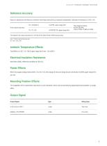
DATASHEET PRESSURE TRANSMITTER AT5020 Reference Accuracy Based on standards and reference conditions including linearity (BFSL), hysteresis, repeatability. Calibration temperature is 20°C + 5°C . +£0.075% upper range limit +0.00075TD% upper range limit linear output accuracy The square root output accuracy is 1.5 times of the above linear reference accuracy Note 1: TD (Turn down) is the range ratio TD = URL/1 URV- LRVI Ambient Temperature Effects Total effect is + (0.1 + 0.1TD) % upper range limit from - 20 to 80°C. Electrical Insulation Resistance More than 20MQ, reference condition at 100V...
Open the catalog to page 5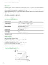
DATASHEET PRESSURE TRANSMITTER AT5020 Time Index = Total damping time constant equal to the sum of the damping time constants of the electronic circuit components and the sensor casings. = Electronic circuit component damping time is adjustable form 0 to 100s. = Experimentally, the damping time of the sensor capsule (separating the sensor diaphragm and the silicone oil filling liquid) is less than 0.2s. = Start-up time after power failure is less than 6s. = Data recovery time to normal use is less than 31s. Environmental Conditions Ambient Temperature Storage Temperature -40 to 110°C , integrated...
Open the catalog to page 6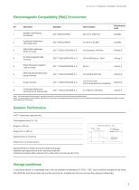
DATASHEET PRESSURE TRANSMITTER AT5020 Electromagnetic Compatibility (EMC) Environment SN Test Items Test Condition Performance Level Radiation interference (Enclosure) Conducted interference (DC power port) Electrostatic discharge (ESD) immunity RF electromagnetic field immunity Power frequency magnetic field immunity Electrical fast transient pulse group immunity . . Surge immunity 1 kV (Line to line) 2 kV (Line to ground) (1.2us/S0us) Conducted interference immunity for RF field sensing Note 1: In the case of performance class A, the performance is normal within the limits of the technical...
Open the catalog to page 7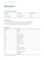
DATASHEET PRESSURE TRANSMITTER AT5020 Menu Functions Pressure Transmitter Transmission Module Type Output Signal Local Control Remote Control Display Screen =m PV: main screen displays process variables, secondary screen displays precentage and progress bar. ™ mA: main screen displays current value, secondary screen displays percentage and progress bar. = %: main screen displays percentage, secondary screen displays percentage and progress bar. Process Unit Process Unit Pounds per square inch Meter mercury column at 0°C Gram per square centimeter Kilogram per square centimeter Standard atmospheric...
Open the catalog to page 8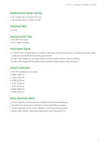
DATASHEET PRESSURE TRANSMITTER AT5020 Measurement Range Setting m URV: up range value, 20 mA upper limit value. = LRV: low range value, 4 mA lower limit value. Analog Output Type = mALINER: linear output. square root output. Fault Alarm Signal m= ALARM NO: when the applied pressure exceeds the upper and lower limits of the range, it is output as normal to the alarm current value, and the lower limit to 3.8 mA, upper at 20.8 mA. = ALARM H: alarm display when the applied pressure exceeds the upper and lower range limits 20.8 mA. = ALARM L: alarm display when the applied pressure exceeds the upper...
Open the catalog to page 9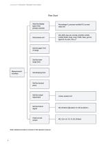
DATASHEET PRESSURE TRANSMITTER AT5020 Flow Chart Sets the display type of the primary variable Percentage %, process variable PV, current value mA kPa, MPa, bar, psi, mmHg, mmH20, mH20, inH20, ftH20, inHg, mHg, TORR, mbar, g/cm2, kg/em2, Pa, atm, mm, m Set the upper limit of range Set the lower range limit Set the output signal type Linear, square root Set fault alarm signal NO, 20.8mA high alarm H, 3.8 low alarm L Fixed current output Note: detailed procedure is shown in the operation manual.
Open the catalog to page 10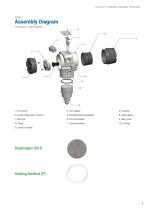
DATASHEET PRESSURE TRANSMITTER AT5020 Assembly Diagram Pressure Transmitter 4. Local configuration buttons 5. Stainless steel Nameplate
Open the catalog to page 11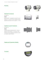
DATASHEET PRESSURE TRANSMITTER AT5020 Standard Connector Plug: M20 x 1.5 Gland : glands size M20 x 1.5 applicable wire diameter 6 to 8mm (optional 11 to 17mm) with 1/2 NPT threaded connection, applicable wire diameter 6 to 8mm, (optional 11 to 17mm). Explosion-proof Connector Plug: M20 x 1.5 Gland : threaded connection, glands size is M20 x 1.5 for wire diameter 6 to 8mm (optional 11 to 17mm) and 1/2NPT threaded connection, applicable wire diameter 6 to 8mm, Display and Operation Module
Open the catalog to page 12All Hollysys catalogs and technical brochures
 HOLLiAS MACS DCS
24 Pages
 LX SERIES PLC CATALOG
14 Pages
 T800K
T800K6 Pages
 LEVEL SWITCH
6 Pages
 MAGNETIC LEVEL GAUGE
12 Pages
 Field Instruments
20 Pages
 PLC Automation
34 Pages


- Valve
- Control valve
- Flowmeter
- Stainless valve
- Ball valve
- Volume flow monitor
- Pneumatic valve
- Actuator
- Regulating valve
- Linear actuator
- Automation software solution
- Management software solution
- Electric actuator
- Packing machine
- Electric valve
- Analysis software solution
- Process software
- Level limit switch
- Windows software