- Products
- Catalogs
- News & Trends
- Exhibitions
Differential Pressure Transmitter AT5010
1 /54Pages

Differential Pressure Transmitter AT5010
1 /54Pages
Catalog excerpts

Differential Pressure Transmitter = SIL2/3 certification = Accuracy up to £0.05% FS = 10-year stability of +0.1% of URL = Combination of more complex level and volume flow measurements possible = Convenient and user-friendly, wide options in forms and material = -500 kPa to 10 MPa (minimum range 0 to 100 Pa) = Precision in measurement = Static pressure up to 40 MPa = Exploration in our range of state-of-the-art differential = Intuitive interface and built-in buttons for quick commissioning of the device = $S316L/HC/Tantalum/SS316L coated with PTFE/SS316L gold plated/Incone! 625 etc. = HART 7.0/Modbus-RTU and others pressure transmitters = Unrivaled precision for accurate industrial measurements = Features, specifications and applications covered in detail = SIL, NACE, NEPSI, ATEX, CE, PMI, EN10204 = Multiple standard process connections, as well as filler fluids, enabling connection to various forms of piping, connection standards are according to EN, ASME/ANSI, GB, GOST, JIS ete.
Open the catalog to page 1
AT5010 Differential Pressure Transmitter 01 Menu Functions Assembly Diagram Dimensional Drawing Factory Settings AT5010 Single Flange Level Transmitter 21 Menu Functions Dimensional Drawings Factory Settings AT5010 Dual Flange Level Transmitter 34 Menu Functions Dimensional Drawings Factory Settings Three-Way Manifold Five-Way Manifold
Open the catalog to page 2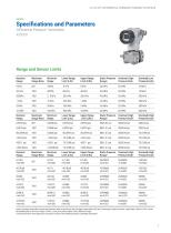
DATASHEET DIFFERENTIAL PRESSURE TRANSMITTER AT5010 Specifications and Parameters Differential Pressure Transmitter AT5010 Range and Sensor Limits Nominal Range Maximum Range Ratio Minimum Range Lower Range Limit (LRL) Upper Range Limit (URL) Static Pressure Range* Overload (High Pressure End) Nominal Range Maximum RangeRatio Minimum Range Lower Range Limit (LRL) Upper Range Limit (URL) Static Pressure Range* Overload (High Pressure End)* Overload (High Pressure End)* Nominal Range Maximum Range Ratio Minimum Range Lower Range Limit (LRL) Upper Range Limit (URL) Static Pressure Range Overload...
Open the catalog to page 3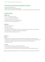
DATASHEET DIFFERENTIAL PRESSURE TRANSMITTER AT5010 Performance Test Standards and Reference Conditions = Test standard GB/T28474/IEC60770. = Reference condition the range is started from zero point. = Silicone oil filled, 316L stainless steel isolation diaphragm, 4 to 20 mA analog output, terminal-base fine adjusted to set value. Vibration Testing Vibration Test = 5Hz
Open the catalog to page 4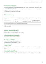
DATASHEET DIFFERENTIAL PRESSURE TRANSMITTER AT5010 Performance Indicators = Overall performance includes but not limited to "Reference accuracy" , "Ambient temperature effect", "Static pressure effect" and other effects of the combined error. = Typical accuracy : +0.05% upper range limit = Annual stability: +0.2% upper range limit per 10 years Reference Accuracy Based on standards and reference conditions including linearity (BFSL), hysteresis, repeatability. Calibration temperature is 20°C + 5°C. +0.05% ® Upper range limit imi +0.005 TD% upper range limit Linear output accuracy
Open the catalog to page 5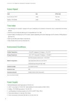
DATASHEET DIFFERENTIAL PRESSURE TRANSMITTER AT5010 Output Signal Code Wiring Type Time Index = Total damping time constant equals to the sum of damping time constants of electronic circuit components and sensor casings. = Electronic circuit component damping time is adjustable from 0 to 100s. = Experimentally, the damping time of the sensor capsule (separating the sensor diaphragm and the silicone oil filling liquid) is less than 0.2s. = Start-up time after power failure is less than 6s. = Data recovery time to normal is less than 31s. Environment Conditions Ambient Temperature Storage Temperature...
Open the catalog to page 6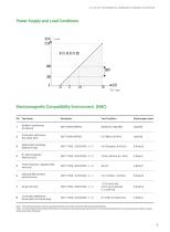
DATASHEET DIFFERENTIAL PRESSURE TRANSMITTER AT5010 Power Supply and Load Conditions Electromagnetic Compatibility Environment SN_ Test Items Test Condition Performance Level Radiation Interference 3 _ Flectrostatic Discharge (ESD) Immunity 4 _ field RF electromagnetic immunity ¢ _ burst Electrical fast transient immunity 1 kV (Line to line) 2 kV (Line to ground) (1.2 us/50 us) Conducted interference Powerfrequency magneticfield Conducted interference immunityfor RF field sensing Note 1: In the case of performance class A, the performance is normal within the limits of the technical specifications...
Open the catalog to page 7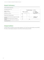
DATASHEET DIFFERENTIAL PRESSURE TRANSMITTER AT5010 Dynamic Performance HART? transmitter response time Total response time (Td + Tc) Transmitter Output vs. Time Tg = Deactime Te = Timeconstant Refresh rate is 10 times per second Standstill time and refresh rate are suitable for all models and ranges. Standardized total response time at 25°C reference conditions. Excluding conversion block response time, analog input module execution time. Storage Conditions It should be stored in a ventilated room with an ambient temperature of -10°C to 55°C and a relative humidity not more than 85% BH, it does...
Open the catalog to page 8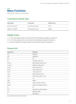
DATASHEET DIFFERENTIAL PRESSURE TRANSMITTER AT5010 Menu Functions Differential Pressure Transmitter Transmission Module Type Output Signal Local Control Remote Conirol PV: main screen displays process variables, secondary screen displays percentage and lm mA: main screen displays current value, secondary screen displays percentage and progress bar = %:main screen displays percentage, secondary screen displays percentage and progress bar Process Unit Process Unit Pounds per square inch Meter mercury column at 0°C Gram per square centimeter Kilogram per square centimeter Standard atmospheric pressure...
Open the catalog to page 9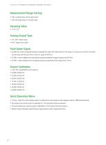
DATASHEET DIFFERENTIAL PRESSURE TRANSMITTER AT5010 Measurement Range Setting m URV: up range value, 20 mA upper value = LRV: low range value, 4 mA lower value Analog Output Type = MA LINER: linear output =m mAv: square root output Fault Alarm Signal m= ALARM NO: when the applied pressure exceeds the upper and lower limits of the range, it is output as normal to the alarm current value, and the lower limit to 3.8 mA, upper at 20.8 mA. = ALARM H: alarm display when the applied pressure exceeds the upper range limits 20.8 mA. = ALARM L: alarm display when the applied pressure exceeds the lower range...
Open the catalog to page 10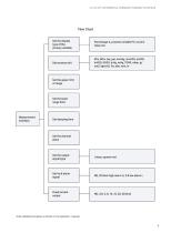
DATASHEET DIFFERENTIAL PRESSURE TRANSMITTER AT5010 Flow Chart Set the display type of the primary variable Percentage %, process variable PV, current value mA inH20, ftH20, inHg, mHg, TORR, mbar, g/ cm2, kg/cm2, Pa, atm, mm, m Set the upper limit of range Set the lower range limit Set the output signal type Linear, square root Set fault alarm signal NO, 20.8mA high alarm H, 3.8 low alarm L Fixed current output Note: detailed procedure is shown in the operation manual
Open the catalog to page 11All Hollysys catalogs and technical brochures
 HOLLiAS MACS DCS
24 Pages
 LX SERIES PLC CATALOG
14 Pages
 T800K
T800K6 Pages
 LEVEL SWITCH
6 Pages
 MAGNETIC LEVEL GAUGE
12 Pages
 Pressure Transmitter AT5020
32 Pages
 Field Instruments
20 Pages
 PLC Automation
34 Pages


- Valve
- Control valve
- Flowmeter
- Stainless valve
- Ball valve
- Volume flow monitor
- Pneumatic valve
- Actuator
- Regulating valve
- Linear actuator
- Automation software solution
- Management software solution
- Electric actuator
- Packing machine
- Electric valve
- Analysis software solution
- Process software
- Level limit switch
- Windows software