- Catalogs
- Holland Shielding Systems BV
- innovative EMI shielding solutions
innovative EMI shielding solutions
1 /286Pages

innovative EMI shielding solutions
1 /286Pages
Catalog excerpts
engineering shielding innovative EMI shielding solutions
Open the catalog to page 1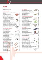
INDEX 101 Shielding tips and tricks Clip-on PCB shielding system 1500 Clip-on PCB shielding cans with cover 1505 PCB clips Large clip (for 1500 series) LC Medium clip (for 1500 series) MC Small pin (for 1500 series) P Tiny clip (for 1500 series) TC Tiny corner clip (for 1500 series) TCC Ultra tiny clip (for 1500 series) UTC Ultra tiny corner clip (for 1500 series) UTCC Fixed PCB shielding cans 1510 - 1515 Fixed PCB shields 1600 Drawn PCB shields 1700 Compartment shielded foam 1800 Conductive foil PCB shielding gaskets 1550 Conductive rubber PCB shielding gaskets 1560 Conductive silicone PCB shielding...
Open the catalog to page 2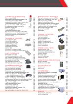
COATINGS, GLUES & SEALANTS Thermal grease 1100 Silver-filled conductive silicone grease 1110 Conductive nickel coating 3800N conductive silver plated copper coating 3800C Conductive transparent paint 3821 Transparent coating with flexibility 3822 2 component coating for floors 3823 Wallshield coating 3824 Silver coating 3830 Conductive metalization 3838 High temperature conductive coating 3840 Electrically conductive glue (shieldokit) 3980 Electrically conductive glue needle 3981 Shieldoseal 3991 TRANSPARENT SHIELDING Mesh foil 9000 - 9300 Conductive mesh 8900 Copper grid PET film 9400 Shielded...
Open the catalog to page 3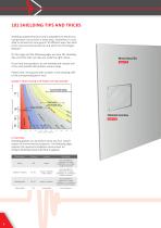
101 SHIELDING TIPS AND TRICKS Shielding radiated emission and susceptibility of electronics components can be done in many ways. Sometimes it is possible to achieve the same goal in 10 different ways. But what is the most economical manner and which has the longest lifespan? On this page and the following pages we have 101 shielding tips and tricks that can help you make the right choice. Metal door/lid Level ||| B If you have any questions, do not hesitate and contact one of our enthusiastic EMI problem solvers today. Please note, red squares with numbers in the drawing refer to the corresponding...
Open the catalog to page 4
» 101 SHIELDING TIPS AND TRICKS Cable shielding tube Level ||| G Absorber foam EMI-IP gaskets Level ||| E PCB shielding cover Level || Honeycomb ventpanel with EMI gasket Level ||| E Power line filter Level ||| E Entry plate Level ||| C Recess areas GASKET SELLECTION & GALVANIC CORROSION Gasket material Flat cable shielding Level ||| G Enclosed material Connector gasket Signal line filter EMI-IP gasket Level Zinc die-casting alloy Zinc plating on steel, chromate passivated Cadmium plating on steel Aluminum, wrought, cast A1 Iron and steel: not corrosion resisting Aluminum allow/Amucor Chromium...
Open the catalog to page 5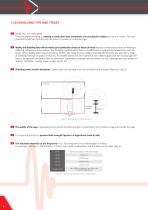
» 101 SHIELDING TIPS AND TRICKS 1 PRINCIPLE OF SHIELDING The principle of shielding is creating a conductive layer completely surrounding the object you want to shield. This was invented by Michael Faraday and this system is known as a Faraday cage. Ideally, the shielding layer will be made up of conductive sheets or layers of metal that are connected by means of welding or soldering, without any interruptions. The shielding is perfect when there is no difference in conductivity between the used materials. When dealing with frequencies below 30 MHz, the metal thickness affects shielding effectiveness....
Open the catalog to page 6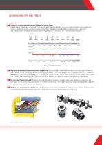
» 101 SHIELDING TIPS AND TRICKS WAVES A wave is a combination of electric field and magnetic fields. A electromagnetic wave is composed of a magnetic part depending on the electric current (ampere), and an electrical section, depending on the electrical voltage (volts). Near the source (near-field) the magnetic part is dominant. At a greater distance, the electrical part and the magnetic part are present in a fixed ratio (far field). (Fig. 7) Figure 7: Wavelength vs. Frequency The material thickness determines which frequencies are blocked from penetrating into or out of the cage. For low frequencies...
Open the catalog to page 7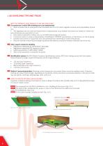
» 101 SHIELDING TIPS AND TRICKS WHY THE FARADAY CAGE PRINCIPLE FOR EMI SHIELDING? 11 Circumstances in which EMI shielding has to be implemented • When a product has to meet government standards like CE or FCC which regulate immunity and compatibility of products. • The regulations do not cover the requirements of daily practice (e.g. medical instruments are tested at 3 meters distance while they are used within 15 cm). • Extra safety is desired for military use, e.g. for EMP (electromagnetic pulses). • If someone wants to create increased levels of shielding for TEMPEST requirements, so that...
Open the catalog to page 8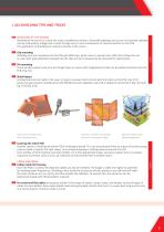
» 101 SHIELDING TIPS AND TRICKS 16 SHIELDING AT THE SOURCE Shielding at the source is usually the most cost-effective solution. Generally speaking, the source of unwanted radiation can be produced by voltage and current through one or more components or interconnections on the PCB. The application of shielding can reduce it directly at the source. Shielding cans are mounted onto the PCB with SMD clips, which come in several sizes. After the re-flow, the can (a cover with walls attached) is placed into the clips and can subsequently be removed for adjustments. There are also systems with pins...
Open the catalog to page 9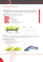
» 101 SHIELDING TIPS AND TRICKS CABLE SHIELDING 23 The housings themselves, i.e. the rack, the box, the enclosure, the metalized box, and the Faraday cage they constitute the main cover of the entire system and also the connection to the outside world. Housings are equipped with displays, entries for power and signal lines, and cooling air-vents. For more information see the case at the beginning of this article. Level III A Level III B Level III C Level III D Level III E Level III F Level III G Level III H Level III I 24 Elements that can reduce the effectiveness of a Faraday cage Seams (Fig....
Open the catalog to page 10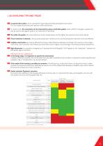
» 101 SHIELDING TIPS AND TRICKS 27 A superior flat surface can be achieved by machining and finally grinding the top surface. This is an expensive process and requires a stiff construction. 28 To reduce costs, the connection can be improved by using a conductive gasket, which will fill in any gaps. A gasket can also be used to seal against water or to meet other IP demands. 29 The softer the gasket, the more tolerance can be compensated, and the lighter the eventual construction will be. 30 If more tolerance is allowed, a less accurate production method can be used and production becomes more...
Open the catalog to page 11All Holland Shielding Systems BV catalogs and technical brochures
 THERMAL PADS 1150
1 Page
 MICROWAVE ABSORBER FOAM 3500
2 Pages
 CLIP-ON GASKET 6500
7 Pages
 STANDARD SHIELD 7000
2 Pages
 Clip-on gasket Catalog
14 Pages
 EMI shielding catalog
64 Pages

Archived catalogs
 Full Catalogue
28 Pages
 Profile Selection Guide
1 Page

