- Catalogs
- Höcherl & Hackl
- ZS/ZSLC/ZSLV Series
ZS/ZSLC/ZSLV Series
1 /23Pages

ZS/ZSLC/ZSLV Series
1 /23Pages
Catalog excerpts

System bus Analog Analog isolated Electronic Loads, ZS Series Voltage up to 800 V Currents up to 2,250 A Power 500 W ... 28.8 kW Depending on model, temporary overload capacity Current, voltage, resistance, power mode Full electronic protection Analog measurement outputs for voltage and current Analog control input MPP tracking Dynamic function with synchronized data logging Dynamic loads SCPI programming with measurement function Application Notes Software Dynamic and Control Time Voltage Switching Remote Control The inbuilt modular enables two have the four operating modes peak-free voltage...
Open the catalog to page 2
ZSLV In the operating modes CC, CV Covers are available as contact design and can also be used as protection for units for danger- solid copper rails with screw connectors. Analog Measurement Outputs There measurement signals available Analog Control for voltage, current and power. The GND terminals can float ±2 V with respect to the negative load input (also optionally iso- Application Notes lated - Option ZS06). Cooling The units are air-cooled. To keep the operating noise low, the fans are temperature From 5 height units there are retractable handles on the top of the device. current-dependently...
Open the catalog to page 3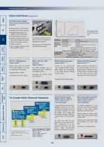
Data Interfaces Extended Function Range When Using an Optional Data Programming in SCPI Syntax Settings with 16 Bit resolution Measurement function for Data logging with constant scanning ZSLV PMLI voltage, current and power Programmable load profile Dynamic operation with variable current rise and fall speed Resolution 16 bits Accuracy see Technical Data MeasureResolution 18 bits ment func- Sampling rate approx. 300 ms for V+I, not syntion Accuracy chronized Current: ±0.2 % of MV ±0.05 % of range Voltage: ±0.1 % of MV ±0.05 % of range Meas. data memory: max. 2000 V/I values + time Loadprofile...
Open the catalog to page 4
Data Acquisition Tool Data Acquisition Tool (Option ZS13-15) The Data Acquisition Tool expands the range of the device by with variable scanning rate for waveform. Simultaneous Fast synchronized data log- ging for waveform genera- Exponential inrush currents fast 15 Bit A/D converter Simultaneous measurement of voltage and current min 200 μs, can be programmed separately for each wave section and synchronized with waveform generator 2000 V/I value pairs with timestamp Solar Panel Test Battery Capacity Test Converter (in addition to 18 Bit standard A/D converter) Sampling rate Synchronization...
Open the catalog to page 5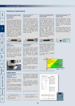
Hardware Expansions Electrically Isolated Analog In the case of potential differences between the nega-tive load input Interface the standard Analog I/O card can be replaced with an isolated version. All measurement and control signals are trans- mitted via isolation amplifiers and compatible with the standard Analog I/O card. The isolation voltage is 500 V DC with respect to the negative load input. screwed onto large devices for easier transport. A 19" rack can then often be dispensed with. This option is available for de- vices from 5HU and is suitable only for hard floors. Factory Calibration...
Open the catalog to page 6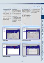
Basic Communication Tool As well as device control, meas- The Basic Communication Tool ured data can be logged and Load Control mands for test purposes and for Individual devices and multi- The following measured values can be selected: Current - Volt- The range of functions includes Waveform Editor with saving the intelligent generation of load MPP Tracking Solar panels can be tested in combination with Option ZS13. Voltage, current and power are displayed numerically. profiles in the form of straight sections. The load waveform is displayed on entry. The profiles can be saved. ZSAC Battery...
Open the catalog to page 7
500 W ... 800 W DC Model (order number) Continuous power Resistance setting Power setting Load connections Zero-Volt option Power consumption Noise max. Current setting Rise/fall time Short-time power Model (order number) Voltage Accessories Application Notes Continuous power Current setting Resistance setting Power setting Rise/fall time Load connections Zero-Volt option Weight Housing Each range of the higher voltage classes of the same device power can also be selected as current range. Level and duration of the peak power, see diagram on page 31 Power consumption Noise max. Short-time power...
Open the catalog to page 8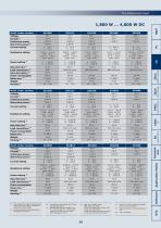
Load connections 5) Zero-Volt option 6) Power consumption Noise max. 7) Weight Housing 8) Model (order number) Continuous power Rise/fall time Load connections Power consumption Noise max. Weight Housing Continuous power Model (order number) Voltage Current Short-time power Current setting Resistance setting Power setting Rise/fall time Load connections Power consumption Noise max. Weight Housing Each range of the higher voltage classes of the same device power can also be selected as current range. Level and duration of the peak power, see diagram on page 31 Power setting Application Notes Resistance...
Open the catalog to page 9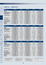
ZSLV PMLI Accessories Application Notes Model (order number) Voltage Current 1) Continuous power Short-time power 2) Current setting Resistance setting Rise/fall time 4) Load connections 5) Power consumption Noise max. 6) Weight Housing Power consumption Noise max. 6) Weight Housing 7) Power setting Load connections Rise/fall time Power setting Resistance setting Model (order number) Voltage Current 1) Continuous power Short-time power 2) Current setting Continuous power Model (order number) Voltage Current Short-time power Resistance setting Power setting Rise/fall time Weight Housing Power...
Open the catalog to page 10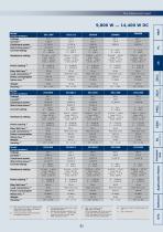
Model (order number) Voltage Continuous power Resistance setting Rise/fall time 4) Load connections 5) Power consumption Noise max. 6) Weight Housing 7) Model (order number) Voltage Continuous power Short-time power Current setting Resistance setting Power setting Rise/fall time Load connections Power consumption Noise max. Weight Housing Each range of the higher voltage classes of the same device power can also be selected as current range. Level and duration of the peak power, see diagram on page 31 Current setting Power setting Model (order number) Voltage Current 1) Continuous power Short-time...
Open the catalog to page 11All Höcherl & Hackl catalogs and technical brochures
 PMLA Series
10 Pages
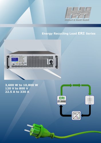 Brochure ERI Series
12 Pages
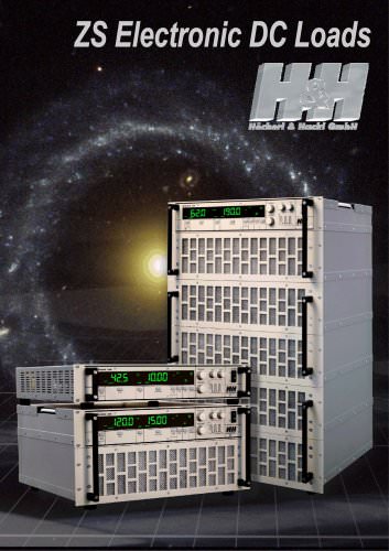
 ZS Series
12 Pages
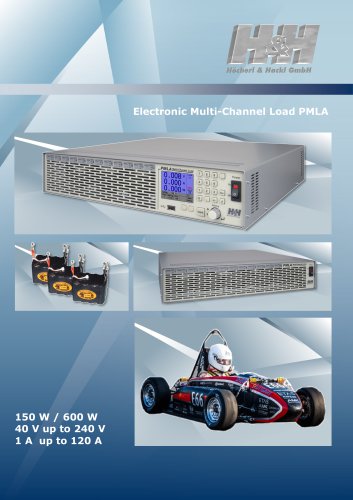 Brochure PMLA
14 Pages
 PLA Series Brochure
16 Pages
 PMLI Series
6 Pages
 PL Series
5 Pages
 Main catalogue
76 Pages
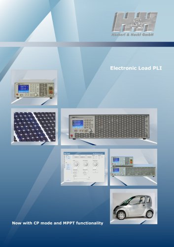 Electronic Loads, PLI Series
5 Pages
 PMLI Multiload
4 Pages
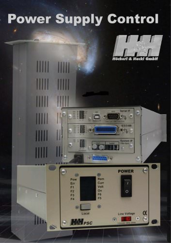 Power Supply Control
4 Pages
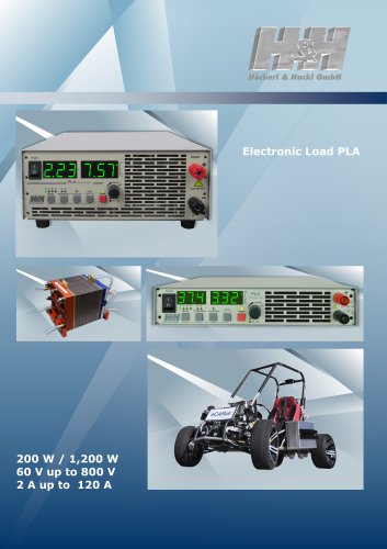
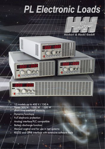 PL Electronic Loads
4 Pages
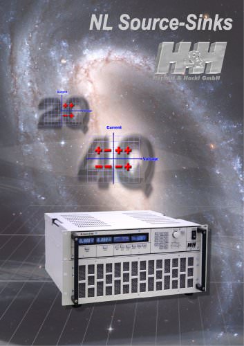 NL Source-Sink
12 Pages
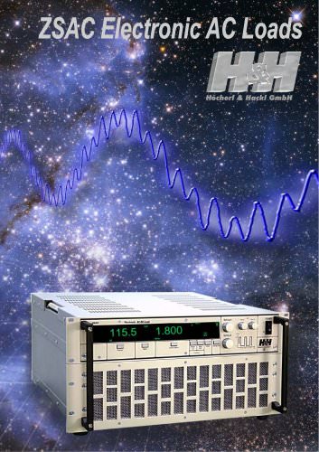 ZSAC Electronic AC Loads
12 Pages
 H&H Product Overview
4 Pages

Archived catalogs
 NL Series
11 Pages
 NL SERIES_2013
11 Pages