
- Catalogs
- Höcherl & Hackl
- NL Series


NL Series

NL Series
Overview
The Source-Sink NL Series electronic loads offer power handling from 200 VA up to 3,120 VA, voltage ranges between 10 V and 80 V, and current capabilities from 2 A to 320 A. Designed for precise source and sink operations, these devices support rapid switching and versatile control options suitable for laboratory and industrial testing.
Main Features
- Available in 2-quadrant and 4-quadrant versions enabling sourcing and sinking of current and voltage.
- Automatic mode switching between source and sink based on test conditions.
- Operating modes include constant voltage and constant current with independently adjustable limits.
- Analog measurement outputs (0–10 V) for real-time voltage and current monitoring.
- Analog control inputs for real-time adjustment of output voltage/current and limits.
- Standard interfaces: USB and RS-232; optional GPIB, LAN, and isolated analog I/O.
- Programmable waveforms and SCPI command set for automated testing.
- Software tools for battery testing, data logging, and waveform generation.
Operating Modes and Quadrant Functionality
2-quadrant units operate with positive output voltage and can source or sink current, starting from -1 V for stability with long leads, effectively acting as limited 4-quadrant devices. True 4-quadrant units handle both positive and negative voltages and currents.
Mechanical and Cooling Design
- Robust 19" rack-mount design, suitable for cabinet or tabletop use.
- Retractable handles on units 5 HU and above; optional castors for heavy units.
- Rear-side connections with binding posts or solid copper bars supporting various cable types.
- Air-cooled with temperature and current-dependent fan control to minimize noise.
Remote Control and Safety
- Full remote control via analog I/O interface with logic-level control for mode selection, output enable, and control speed.
- Optional electrically isolated analog I/O interface providing up to 500 V DC isolation for safe operation with potential differences.
- Safety covers available for output terminals to protect against hazardous voltages.
Hardware Expansions
- GPIB interface card (option ZS03) for enhanced connectivity.
- Power I/O card (option ZS07) with 8 relay outputs and 8 logical inputs isolated from load output.
- Castors (option ZS09) for mobility of large devices.
- Factory Calibration Certificate (FCC) compliant with DIN EN ISO 9000; free recalibration within 2 years.
- Data Acquisition Tool (option NL13) for fast synchronized data logging with waveform generation and timestamped memory.
- Ethernet to RS-232 converter (option ZS15) for network communication.
- Electrically isolated analog I/O interface (option NL06) for safe signal transmission with potential differences.
Software Tools
- Control Tool: Standard software for device configuration, data logging, trigger management, and cut-off criteria activation.
- Dynamic List and Data Acquisition Tool: Enables graphical waveform creation, storage, and fast synchronous data logging (requires NL13 option).
- Battery Test Tool: Supports charging, discharging, cycling, capacity determination, and logging for energy storage units with configurable cut-off criteria and test profiles; generates reports and exports data.
Technical Specifications and Model Overview
The NL Series includes unipolar devices with voltage ranges from -1 V to +100 V, current ranges from ±2 A to ±320 A, and power ratings from 200 W up to 3,600 W (models up to 6 kW available on request). Rise/fall times for current and voltage are typically 200 µs. Terminals vary by model and include binding posts, flat copper bars, bolts, and safety sockets. Power consumption and mains supply options depend on model power level. Dimensions range from 2 HU (88 mm height) to 11 HU (488 mm height) rack units, with weight scaling accordingly.
A detailed table lists model numbers with their voltage/current/power ratings, terminal types, power consumption, dimensions, and housing details.
Mechanical and Installation Details
- Designed for 19" rack installation; heights from 2 HU to 14 HU depending on power.
- Typical width 483 mm; depth and height vary by model.
- Sliding rails recommended due to device weight.
- Terminal types include flat copper bars, bolts, binding posts, and safety sockets.
- Optional castors increase height clearance for mobility.
Electrical and Measurement Accuracy
- Voltage measurement accuracy: ±0.1% of range (±0.05% typical).
- Current measurement accuracy: ±0.2% of range (±0.05% typical).
- Resolution: 18 bits standard; 13 bits with Data Acquisition Tool (NL13).
- Sampling rate: 330 ms standard (non-triggerable); 200 µs with data acquisition option.
- Setting accuracy for voltage/current: ±0.1% to ±0.2%.
- Ripple: 0.05% RMS of range.
- Load effect: 0.1% from 0 to 100% load.
- Line effect: ±0.02% for ±10% line voltage variation.
- Analog control accuracy and measurement outputs specified with offsets and input resistances.
Protection and Safety Features
- Overcurrent protection and overtemperature cut-off included.
- Voltage and current protection accuracy: ±0.1% to ±0.4%.
- Operating temperature range: 5 °C to 40 °C; storage -25 °C to 65 °C.
- Maximum operating altitude: 2000 m.
- Pollution degree 1 and overvoltage category II compliance.
- Cooling via temperature and current-controlled fans with front-to-rear airflow.
- Protection class IP20.
- Electrical safety standards: DIN EN 61010-1 and DIN EN 61010-2-030.
- EMC compliance: DIN EN 61326-1, DIN EN 55011, DIN EN 61000-3-2, DIN EN 61000-3-3.
Additional Features and Options
- Parallel operation of up to 3 devices in Master-Slave mode (hardware-controlled in current mode).
- External control functions include standby, operating mode change, trigger input/output, and remote shutdown.
- Power supply options: 115/230 V AC ±10%, 50-60 Hz; some models support 230/400 V AC - 16 A CEE.
- Factory calibration certificate provided with two free recalibrations.
- Warranty period: 2 years.
Installation and Usage Notes
- Allow approximately 100 mm additional depth for rear cable connections in 19" rack installations.
- Sliding rails are mandatory for safe installation due to device weight.
- Class C protective equipment recommended for mains supply due to high inrush current.
- Minimum load capacity for analog measurement outputs is 2 kΩ.
Manufacturer Information
Höcherl & Hackl GmbH
Industriestraße 13, 94357 Konzell, Germany
Phone: +49 9963/94301-0
Fax: +49 9963/94301-84
Email: [email protected]
Website: www.hoecherl-hackl.com
Note: All technical data apply at ambient temperature of 21 °C. Specifications are subject to change without notice.
Catalog excerpts

Power Distribution Source-Sink AC & DC Multi-Channel Mulit-Channel, GUI Energy Recycling Multi-Range High Power Low Power H&H Source-Sink, NL Series Interface overview • 2-quadrant or 4-quadrant versions • Source-sink function • Rapid regulation time • Current and voltage mode • Adjustable limitations • Analog measurement outputs for voltage and current • Analog control inputs • USB + RS-232 interface • Programmable waveform • SCPI programming with measurement function • Software tools for battery testing SCPI Operating Modes The NL source-sinks can operate in constant voltage...
Open the catalog to page 2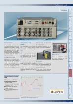
High Power Multi-Range Optional castors can be mounted controlled remotely via the stand- For voltage and current acquisi- No separate installation kits are ard Analog I/O Interface. Operat- tion 0 … 10 V analog measure- needed for 19“ rack installation. ing mode selection, output on/off ment signals are available in real and adjustment of control speed Analog Measurement Energy Recycling Remote Control can be set with logic levels. A version (NL06) which is electrical- the operating noise low, the fans Safety Covers Covers are available for outputs Analog Control Inputs Depending on the selected...
Open the catalog to page 3
Hardware Expansions GPIB Interface Expansion With the ZS03 option the device Data is sent via the LAN card to the Serial Interface of the unit. Electrically Isolated Analog I/O Interface the data interface and 8 logical card can be replaced by an isolated trol signals are transmitted via High Power Interface the standard Analog I/O Supplied without GPIB cable. Simply insert the card. panded to control external devic- between the negative load input In the case of potential differences isolation couplers. compatible with the standard Analog I/O card. The isolation voltage Calibration (FCC-NLxx)...
Open the catalog to page 4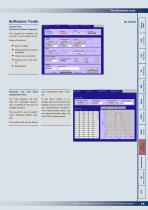
Software Tools Control Tool (Universal Control Program) be used to control single device. Scope of functions: Trigger source selection Activation of cut-off criteria Data logging Energy Recycling and reactivated when needed. The Tool Dynamic List per- mits the intelligent genera- stalled, fast synchronous data tion of profiles in the form of straight sections. ically displayed before testing. be imported directly after the Acquisition Tool Power Distribution Data logging with numerical display High Power Device settings Tool supplied as standard can Subject to modification without notice, errors...
Open the catalog to page 5
Software Tools High Power Battery Test Tool Charging Discharging Cycling Capacity determination Logging Cut-off criteria Dynamic test The Battery Test Tool enables the library.1) At the end of charging or discharging phases there are different monitoring criteria. To test the DUT for specific requirement it is possible to apply a predefined waveform. The most important current test information Current Time Capacity -dV/Cell External event (Option ZS07 required)2) glance. A report can be produced for documentation of the test. The time resolution can be adjusted from 300 ms onwards. Energy Recycling...
Open the catalog to page 6
with safety cover with safety cover 4,400 VA Mains supply Energy Recycling Power consumption Model (order number) Voltage Current Power Rise/ Current fall time 1) Voltage Mains supply Power consumption Measured at short-circuited output terminals (current) and open output terminals (voltage). Tolerance ±20 %. Type of terminals 9) Flat copper bar 25 x 8 mm, vertically installed with screw M10 10) Bolt with thread M8, 20 mm long 11) Binding post for 4 mm pin 12) connector with connection possibility for stripped wire, max. 35 A 13) Touch-protected binding post for 4 mm pin connector with connection...
Open the catalog to page 7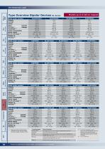
High Power Multi-Range Energy Recycling Mulit-Channel, GUI PMLA PMLI Power Distribution Type Overview Bipolar Devices Model (order number) Voltage Current Power Current Rise/ fall time 1) Voltage Terminals 2) Power consumption Mains supply W x H x D (mm) 3) Weight ca. Housing 4) Model (order number) Voltage Current Power Current Rise/ fall time 1) Voltage Terminals 2) Power consumption Mains supply W x H x D (mm) 3) Weight ca. Housing 4) Model (order number) Voltage Current Power Current Rise/ fall time 1) Voltage Terminals 2) Power consumption Mains supply W x H x D (mm) 3) Weight ca. Housing...
Open the catalog to page 8
High Power Energy Recycling With ZS09 option (castors): 45 mm NL device with FKS25X8-SM10 connections NL SE Subject to modification without notice, errors and omissions expected In the case of 19“ rack systems, sliding rails are needed due to weight. Power Distribution Dimension of terminals when using protective cover
Open the catalog to page 9
Technical Data Technical data apply for an ambient temperature of Ta = 21 °C Voltage protection Current protection Sampling rate (not synchronized) of the measured value (real value) Accuracy of measurement with Data Acquisition Tool (Option NL13), High Power read out via Data Interface of the measured value (real value) Voltage Energy Recycling Mulit-Channel, GUI PMLA PMLI of the measured value (real value) Sampling rate (programmable) Operating conditions Operating temperature Product of voltage and current Stock temperature Quotient of voltage and current minimal 200 µs (to memory) triggerable...
Open the catalog to page 10
Höcherl & Hackl GmbH Industriestraße 13 94357 Konzell DEUTSCHLAND Tel.: +49 9963/94301- 0 Fax.: +49 9963/94301-84 E-Mail: [email protected] http://www.hoecherl-hackl.com NL excerpt from Catalog_E_03.02
Open the catalog to page 11All Höcherl & Hackl catalogs and technical brochures
 PMLA Series
10 Pages
 Brochure ERI Series
12 Pages
 ZS Series
12 Pages
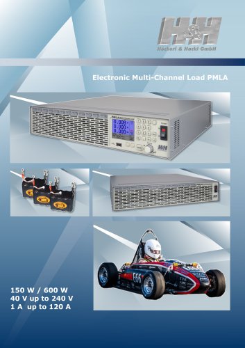 Brochure PMLA
14 Pages
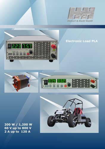 PLA Series Brochure
16 Pages
 ZS/ZSLC/ZSLV Series
23 Pages
 PMLI Series
6 Pages
 PL Series
5 Pages
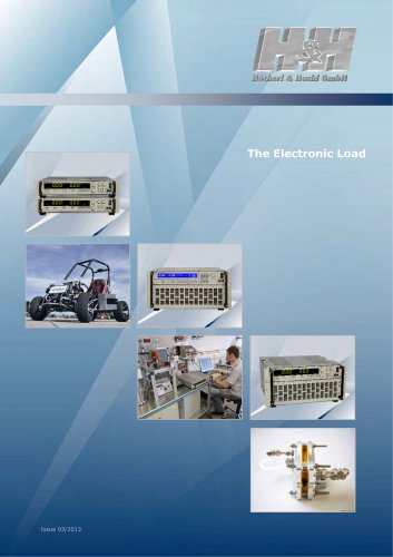 Main catalogue
76 Pages
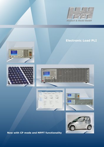 Electronic Loads, PLI Series
5 Pages
 PMLI Multiload
4 Pages
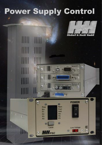 Power Supply Control
4 Pages
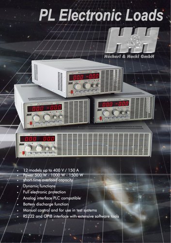 PL Electronic Loads
4 Pages
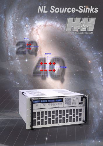 NL Source-Sink
12 Pages
 ZSAC Electronic AC Loads
12 Pages
 H&H Product Overview
4 Pages

Archived catalogs
 NL SERIES_2013
11 Pages