- Catalogs
- HKS Dreh-Antriebe GmbH
- HYDRAULIC ROTARY ACTUATORS FOR INDUSTRIAL APPLICATIONS I-DA-H
- Products
- Catalogs
- News & Trends
- Exhibitions
HYDRAULIC ROTARY ACTUATORS FOR INDUSTRIAL APPLICATIONS I-DA-H
1 /20Pages

HYDRAULIC ROTARY ACTUATORS FOR INDUSTRIAL APPLICATIONS I-DA-H
1 /20Pages
Catalog excerpts

HYDRAULIC ROTARY ACTUATORS FOR INDUSTRIAL APPLICATIONS
Open the catalog to page 1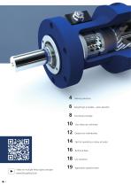
Moving solutions Everything’s included – series benefits Functional principle Tips for operating a rotary actuator Technical data Video on multiple helical gear principle: www.hks-partner.com Your ideas are unlimited Application questionnair
Open the catalog to page 2
The multiple helical gear principle Wherever materials need to be rotated and tilted, precisely accelerated, braked, positioned and held, HKS products are there to help you get the job done – with great precision and endurance. We see “Made in Germany” as the highest standard and the yardstick for the quality of our products at the same time. Innovation is an integral part of everything we do, which is an advantage for you because with HKS products you can always be sure of working with state-of-the-art technology. HKS has its own development department and manufactures practically every part...
Open the catalog to page 3
Moving solutions Ballcocks, armatures Container-tilting appliances Crank drive Doors, gates Cover activation Pipe and sheet metal bending machines Tool changers Linear transport
Open the catalog to page 5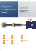
Interleaved gears are surface-hardened › Nearly maintenance-free › Increases effectiveness Everything’s included – series benefits Rotary pistons can be run to their end stop positions and loaded › No external end stops required Rotation angle or end stop query possible via camshaft › Precise positioning of rotation angle › Standard rotation angles 90°, 180°, 270° and 360° Greater working pressure › Up to 20% more power Shaft with bearing Bleed screws Load holding valve (optional, not shown) Sealing ring Regulating screw
Open the catalog to page 6
Improved bearing efficiency with four-point bearing › For handling strong radial and axial forces › For greater longevity Any intermediate rotation angle possible › Customer-specific adaptation and integration into existing systems Improved end position cushioning › Soft braking of mass moments of inertia › Results in greater longevity for the entire system Angular adjustments › Precise travel to rear end position › ±4° angular adjustment State-of-the-art sealing technology › Ensures less wear › Longer service life for the entire system › No internal leakage › Increases safety Infinite adjustment...
Open the catalog to page 7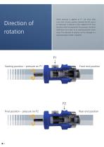
When pressure is applied at P1, the drive shaft turns from its basic position towards the left (counter-clockwise). If pressure is then applied at P2 once the drive shaft has reached its final position, the drive shaft then turns back to its starting position (clockwise). The direction of rotation can be changed in a special-purpose model if required. P1 Starting position – pressure on P1 P2 Final position – pressure on P2
Open the catalog to page 8
Take a moment to find the right moment Mt ≥ ML + MB Mt = Total moment ML = Loading moment MB = Accelerating/braking moment Details regarding calculation If a mass is subjected to a rotating movement with the angle φ in the time tges, from a standstill, external losses (frictional forces) need to be overcome, masses accelerated and subsequently delayed. The total sum of the resulting moments gives the required driving torque for the rotary actuator. When calculating, make sure that the following requirement is met in every possible rotating position: Depending on the position (horizontal, vertical)...
Open the catalog to page 9
Your ideas are unlimited Standard design Shaft versions (with center bore and according to various DIN standards) Shaft with feather key Keyed shaft Hollow shaft (optionally across the entire rotation area) Camshaft with internal thread Pressure-proof proximity switch Angle sensor, potentiometer with coupling and attachment housing 10 Load holding valve Measurement connection
Open the catalog to page 10
Tips for applications engineering Whatever your project, the rotary actuator can be optimally adjusted to handle it. A great many installation and connection options are available as standard, but customer-specific, special-purpose solutions can also be implemented. Hollow shaft with feather key slot Hollow shaft with square Connection options Our technical customer support team will be happy to assist you with any questions you may have regarding special-purpose solutions using a comprehensive approach. Phone: +49-6053-61630 E-mail: [email protected] Standard design Flattened flange Flange...
Open the catalog to page 11
Options for individuality The versions illustrated here are only a few of the numerous options with which HKS rotary actuators can be individually equipped. Proximity switch inductive (PI) Limit switch mechanical (LM) Inductive proximity switch Combination of inductive proximity switch and encoder in the e-box
Open the catalog to page 12
Product code Angle of rotation (90°, 180°, 270°, 360°) optional special angle of rotation Example: Cushioning (standard) Angular adjustment (standard) Camshaft with internal thread M10 (standard) Hollow shaft feather key DIN 6885 Proximity switch inductive Pressure-proof proximity switch Hollow spline shaft// bore ISO 14 Limit switch mechanical Potentiometer/rotary encoder Protective box for limit switch/rotary encoder Load holding valve Bearing for absorbing high FR Using the product code, we design the rotary actuator together with you.
Open the catalog to page 13
Tips for operating a rotary actuator Tips for continuous operation The values specified are effective values and may not be exceeded. When operating in multiple shifts with fast cycle times and very high continuous loads, we recommend taking a safety factor of 70% of the maximum permitted torque into account. It is sometimes necessary to change the hydraulic oil, depending on the size of the system. The smaller the system, the more often the oil needs to be changed. If the hydraulic fluid becomes contaminated in any way, it must be changed without delay. Purity class recommendation: ISO 4406...
Open the catalog to page 14
Screw connection Use the correct tightening torque to assemble the screw connections. Otherwise, the load capacity of the connection is reduced. In the worst case, the connection could even become loose. Tightening torque in Nm for cylinder screws in accordance with DIN EN ISO 4762 (12.9) Rotary actuator for display Pressure fluid Only mineral oils in accordance with Group HLP DIN 51524/ part 2 and VDMA sheet 24318 may be used. Their viscosity must be between 15 mm²/s (cSt.) and 250 mm²/s (cSt.). These conditions are equivalent to the hydraulic oils HLP 16 to HLP 46, depending on temperature....
Open the catalog to page 15All HKS Dreh-Antriebe GmbH catalogs and technical brochures
 MainCatalog
32 Pages
 Rack and Pinion Actuators
9 Pages


- Rototherm linear actuator
- Double-acting cylinder
- Rototherm hydraulic cylinder
- Compact actuator
- Industrial actuator
- Rototherm compact cylinder
- Precision actuator
- Extruded aluminum actuator
- Pneumatic actuator
- Double-acting actuator
- Stainless steel actuator
- Positioning actuator
- Micro actuator
- Control actuator
- Integrated actuator
- Standard actuator
- Hydraulic actuator