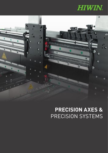
- Catalogs
- HIWIN GmbH
- Catalogue Ball Spline
Catalogue Ball Spline
1 /26Pages

Catalogue Ball Spline
1 /26Pages
Catalog excerpts
BALL SPLINE
Open the catalog to page 1
BALL SPLINE Ball Spline are shaft guides used for precise guidance of linear movements. They consist of a shaft with multiple pairs of longitudinal grooves and a ball spline nut. The nut contains ball cages filled with steel balls. They roll along the longitudinal grooves of the ground shaft and thus enable precise linear movements. Due to the angular arrangement of the force-transmitting elements, Ball Spline can absorb both radial forces and torque loads. DOWNLOADS AND APPLICATIONS Assembly instructions
Open the catalog to page 3
Ball Spline Contents
Open the catalog to page 4
3.1 Ball Screw Splines (FBR type) 9 5.1 Strength design of spline shaft 11 6.2 Conditions and benchmarks for use in the selection of preload 21 7.1 HIWIN order code for Ball Spline FBR and FBL types 22 7.3 Product dimensions and specifications for compound Ball Spline 23 8.2 Material and surface treatment 24 9.1 FB type Ball Spline working mode 25
Open the catalog to page 5
Ball Spline Product overview
Open the catalog to page 6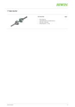
hiwim Ball Screw Spline Page 9 - Driven flange nuts - Shaft with Ball Spline nut and Ball Screw nut - With solid or hollow shaft
Open the catalog to page 7
Ball Spline Features 2. Features The HIWIN Ball Spline is an anti-rotation shaft guide consisting mainly of a nut filled with steel balls and a shaft with several longitudinal grooves arranged in pairs. The steel balls roll in the raceways between the nut and shaft in a closed circuit and enable the nut to move along the shaft with low friction and high precision. The angular contact between the steel balls and the raceway in the nut and shaft enables radial forces and torques to be absorbed. Thanks to the integrated nut/bearing design, the Ball Spline can achieve high payloads with a compact...
Open the catalog to page 8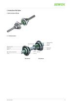
3. Introduction of Ball Spline 3.1 Ball Screw Splines (FBR type) Flange outer ring Steel ball Retainer Steel ball (bearing) Flange outer ring Bearing seal Retainer Bearing seal Spline nut Retainer Spline shaft including thread End cap Steel ball
Open the catalog to page 9
Ball Spline Selecting procedure of Ball Spline 4. Selecting procedure of Ball Spline - Installation space - Operation frequency - Required life - Distance between 2 nuts - Assembly direction Select type and dimensions based on the application conditions. Refer to the classification table. Design of spline strength - Expected diameter - Fixing method of the spline shaft - Allowable load of the spline shaft - Displacement of the spline shaft (bending, torsion) Selecting type Calculate the rated life from the life calculation formula for load capacity. Does it meet the use requirements? Selecting...
Open the catalog to page 10
5. Calculation methods 5.1 Strength design of spline shaft The Ball Spline can absorb radial loads and torsions. Sufficient strength of the Ball Spline must be ensured by calculating the load-bearing capacity and structural safety, especially in the case of high combined loads. 5.1.1 Spline shaft subjected to bending When bending moments act on the spline shaft of the Ball Spline, the most suitable spline diameter can be calculated according to formula F 5.1: F 5.1 M Maximum torque acting on spline shaft [Nmm] σ Allowable bending stress of spline shaft (98 N/mm2) Z Axial section modulus of the...
Open the catalog to page 11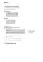
Ball Spline Calculation methods 5.1.3 Spline shaft subjected to bending and torsion simultaneously If the shaft is subjected to bending and torsional loads simultaneously, the required shaft diameter must be calculated separately for the equivalent bending moment (Me) and for the equivalent torsional moment (Te). The values must be compared and the larger of the two calculated shaft diameters must be used. Equivalent bending moment F 5.3 5.1.4 Rigidity of the spline shaft Rigidity of the spline shaft is indicated by the torsional angle of the spline shaft of length 1 m, which is limited to about...
Open the catalog to page 12
5.1.5 Bending and bending angle of the spline shaft The bending and bending angle of the ball spline shaft must be determined by calculation using the formulas corresponding to the actual load conditions. Table 5.1 Calculation of bending and bending angle Support method Both ends are free Calculation formula of bending l/2 Both ends are fixed Both ends are free Both ends are fixed Both ends are fixed Calculation formula of bending angle dmax Maximum bending [mm] I Geometric moment [mm4] P Concentrated load [N] Mo Torque [Nmm] i1 Bending angle at support point p Uniform load [N/mm] l Span moment...
Open the catalog to page 13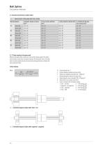
Table 5.2 Characteristics of the spline shaft cross-section When the ball spline shaft is driven by a motor and the rotation speed of the spline shaft increases closely to the resonance frequency, the mechanical stress on the ball spline increases significantly and can lead to bad running performance, vibration and even mechanical failure lb Distance between installation surfaces [mm] E Modulus of longitudinal elasticity [2.06 x 10⁵ N/mm2] I Minimal geometrical moment of inertia [mm4] Y Density (specific center of gravity) [7.85 x 1 05 kg/mm3] A Spline shaft cross-sectional area [mm2] X Factor...
Open the catalog to page 14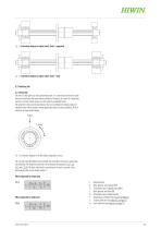
Fig. 5.7 Schematic diagram of spline shaft: fixed - fixed The life of a Ball Spline can vary considerably even if it is manufactured from the same batch and used under the same motion conditions. Therefore, as a basis for calculating the life of a linear motion system, use the rated life as defined below. The rated life is the total running distance that can be achieved by having a batch of identical linear motion systems moving separately under the same conditions, 90 % of which do not show metal fatigue. The running of the Ball Spline can be divided into three types of torsions, radial loads...
Open the catalog to page 15
Calculation methods equivalent radial toad can be calculated according to formula £5.9 and then the life can be calculated. PE Equivalent radial load [N] cosa Constant angle (FBR type: a = 70°) i 3 rows of steel balls under load for specification 20 dp Ball center diameter [mm] Calculating life time After calculating the rated life (L) using the above formulas, the life time can be calculated according to formula £59 when the number of strokes and times are fixed. 5.2.2 Temperature coefficient fT When using a Ball Spline in operating temperatures exceeding 100 °C, multiply the temperature coefficient...
Open the catalog to page 16All HIWIN GmbH catalogs and technical brochures
 Catalogue Electric actuator EA
55 Pages
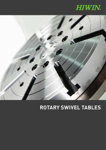
 Catalogue Rotary tables
38 Pages
 Catalogue Servo motors
23 Pages
 Catalogue Linear guideways
154 Pages
 Catalogue strain wave gears
76 Pages
 Catalogue Torque motors
44 Pages
 Catalogue Ballscrews
81 Pages
 catalogue Servo drives
29 Pages
 HIWIN Image brochure
9 Pages


Archived catalogs
- Actuator
- Electric gearmotor
- Linear actuator
- Electric actuator
- HIWIN coaxial gear reducer
- Steel bearing
- HIWIN precision gear reducer
- Servo-motor
- HIWIN compact gear reducer
- Solid-shaft gearhead
- Ball bearing
- HIWIN hollow-shaft gear reducer
- HIWIN gear reducer for industrial applications
- HIWIN rotary table
- Metal nut
- Servo-amplifier
- Screw actuator
- HIWIN shaft gear reducer