- Catalogs
- Hirose Electric Europe B.V.
- BM46 Series
- Company
- Products
- Catalogs
- News & Trends
- Exhibitions
BM46 Series
1 /8Pages

BM46 Series
1 /8Pages
Catalog excerpts
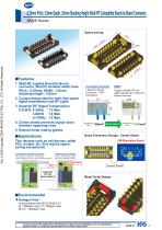
■Features Conventional Connection 1 Board-to-Board Connector + 2 RF Connectors Support multiple RF and digital signals with 1 Board-toBoard connector 1. Multi-RF capable Board-to-Board connector, World’s smallest width class Pitch : 0.35mm, Width : 2.0mm, Stacking height : 0.6mm 2. Contact design ideal for both high speed digital transmission and RF signal 3. Superior RF Signal Transmission V.S.W.R. 0-3GHz : 1.3 Max. 3-6GHz : 1.4 Max. 6-12GHz : 1.6 Max. 4. Center shield prevents signal noise between opposing rows 5. Robust metal mating guides Dec.1.2019 Copyright 2019 HIROSE ELECTRIC CO., LTD. All Rights Reserved. Noise Prevention Design : Center Shield Thin devices such as cell phones, tablet PCs, routers, etc. that require spacesaving components. Conventional Internal Connection RF connection : RF cable + RF connector Other connections : FPC + Board-to-Board connector Connect RF and other signals with FPC and Board-to-Board Other connections Main Board Center Shield Main Board Metal Guide Design S Sub Board ■Environmental Halogen-free* In accordance with IEC 61249-2-21 Br : 900ppm max, Cl : 900ppm max Br+Cl : 1500ppm max In cases where the application will demand a high level of reliability, such as automotive, please contact a company representative for further information.
Open the catalog to page 1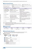
■Product Number Structure Refer to the chart below when determining the product specifications from the product number. Please select from the product numbers listed in this catalog when placing orders. •Header / Receptacle BM46B -* DP - 0.35 V (**) o © © o © © ©No. of Signal Contacts : 12 ©Connector Type DP : Header DS : Receptacle ©Termination Type : Straight SMT ©Gold plating and packaging conditions (51) : Gold plating Embossed tape packaging (20,000 pcs/reel) (53) : Gold plating Embossed tape packaging (1,000 pcs/reel)
Open the catalog to page 2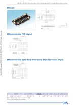
BM46 Series^0.35mm Pitch, 2.0mm Depth, 0.6mm Stacking Height Multi-RF Compatible Board-to-Board Connector Dec.1.2019 Copyright 2019 HIROSE ELECTRIC CO., LTD. All Rights Reserved. ■Recommended PCB Layout ■Recommended Metal Mask Dimensions (Mask Thickness : 80pm) o o +1 CO oJ Note 1 : Please place orders in full reel quantities. Note 2 : This connector has no polarity.
Open the catalog to page 3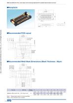
BM46 Series^0.35mm Pitch, 2.0mm Depth, 0.6mm Stacking Height Multi-RF Compatible Board-to-Board Connector Dec.1.2019 Copyright 2019 HIROSE ELECTRIC CO., LTD. All Rights Reserved. ■Recommended Metal Mask Dimensions (Mask Thickness : 80pm) Note 1 : Please place orders in full reel quantities. Note 2 : This connector has no polarity.
Open the catalog to page 4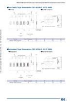
BM46 Series^0.35mm Pitch, 2.0mm Depth, 0.6mm Stacking Height Multi-RF Compatible Board-to-Board Connector BM46 Series^0.35mm Pitch, 2.0mm Depth, 0.6mm Stacking Height Multi-RF Compatible Board-to-Board Connector Dec.1.2019 Copyright 2019 HIROSE ELECTRIC CO., LTD. All Rights Reserved. ■Embossed Tape Dimensions (IEC 60286-3, JIS C 0806) •Header •Reel Dimensions •Receptacle •Reel Dimensions
Open the catalog to page 5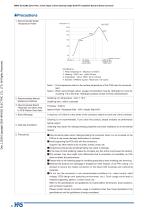
Dec.1.2019 Copyright 2019 HIROSE ELECTRIC CO., LTD. All Rights Reserved. BM46 Series^0.35mm Pitch, 2.0mm Depth, 0.6mm Stacking Height Multi-RF Compatible Board-to-Board Connector
Open the catalog to page 6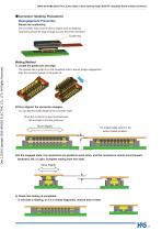
BM46 Series●0.35mm Pitch, 2.0mm Depth, 0.6mm Stacking Height Multi-RF Compatible Board-to-Board Connector ●Connector Handling Precautions Disengagement Prevention Please use cushioning The connector may come off due to impact such as dropping. Cushioning should be large enough to cover the entire connector. Cushioning Dec.1.2019 Copyright 2019 HIROSE ELECTRIC CO., LTD. All Rights Reserved. Mating Method 1) Locate the guide port and align. This product has a guide rib on the receptacle side to ensure proper engagement. Align the connector based on the guide rib. 2)Once aligned, the connector engages....
Open the catalog to page 7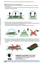
BM46 Series●0.35mm Pitch, 2.0mm Depth, 0.6mm Stacking Height Multi-RF Compatible Board-to-Board Connector ●Handling Precautions for Connector Removal 1) When removing the connector, it is preferable to pull it out in the upward direction from the connector mounting surface. Dec.1.2019 Copyright 2019 HIROSE ELECTRIC CO., LTD. All Rights Reserved. However when removing the FPC from the circuit board it becomes more difficult to remove it vertically with higher pin counts and thin FPCs. 2) If difficult to remove, extract the connector diagonally in the direction of the pitch. Note that removal...
Open the catalog to page 8All Hirose Electric Europe B.V. catalogs and technical brochures
 Connector Selector 2025
134 Pages
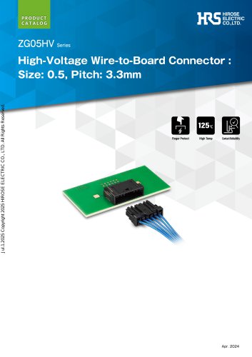 ZG05HV Series
8 Pages
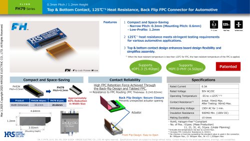 FH79 Series
1 Page
 DF36 Series
14 Pages
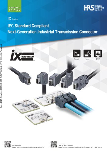
 IX Series
15 Pages
 ZE05 Series
8 Pages
 DF40T Series
1 Page
 FH72 series
12 Pages
- AMOT data connector
- AMOT electrical power supply connector
- AMOT metal connector
- AMOT round connector
- AMOT plastic connector
- Single-pole switch
- AMOT female connector
- AMOT screw-in connector
- AMOT industrial connector
- Junction block
- AMOT circular connector
- AMOT IP67 connector
- AMOT rectangular connector
- AMOT male connector
- Technology switch
- AMOT straight connector
- AMOT cable connector
- AMOT current connector