


IMatrix F30

IMatrix F30
This manual provides comprehensive technical specifications and instructions for the HIMatrix F30 safety-related controller, covering installation, start-up, configuration, operation, maintenance, and decommissioning. It is intended for professionals with specialized knowledge in safety-related automation systems.
Safety
The HIMatrix components are designed for safety-related systems and must adhere to specified guidelines. They operate with SELV or PELV and are suitable for Ex-Zone 2 with additional measures. Key environmental requirements include a protection class of III, an ambient temperature range of 0 to +60 °C, and a supply voltage of 24 VDC. ESD protection is necessary during modifications or replacements.
Product Description
The F30 controller is a compact system with 20 digital inputs and 8 digital outputs, TÜV-certified for safety applications up to SIL 3 and SIL 4. It includes safety-related digital inputs and outputs with configurations for fault reactions and line control.
Start-up
Installation involves connecting digital inputs and outputs, with specific instructions for surges and cable plugs. Configuration is done using SILworX or ELOP II Factory, depending on the processor's operating system.
Operation and Maintenance
Operation includes system handling and diagnosis, while maintenance involves addressing faults, loading the operating system, and conducting proof tests.
Decommissioning, Transport, and Disposal
Guidelines are provided for safely decommissioning, transporting, and disposing of the HIMatrix system.
Specifications
The F30 014 controller operates within a temperature range of -25 to +70 °C and can handle a load of 0.5 A on all outputs between 60 to 70 °C. It is vibration and shock tested according to EN 50125-3 and EN 50155 standards.
Procedures
In case of overload, digital outputs are automatically switched off and resume once the overload is removed. Faulty signals trigger a safe state, and device faults result in all outputs being switched off, indicated by the FAULT LED.
Equipment and Variants
Several controller variants are listed, each with specific operating temperature ranges and compatibility with programming tools.
LED Indicators
LEDs indicate various states such as operating voltage, system status, communication, and I/O activity, with specific blinking patterns and colors.
Communication
The controller supports Ethernet communication with configurable IP addresses and subnet masks, using protocols like safeethernet, Modbus TCP, and EtherNet/IP.
Reset Key
A reset key is available for resetting connection parameters and accounts to default values, requiring a reboot with the key engaged for at least 20 seconds.
Hardware Clock
The controller's hardware clock is powered by an integrated gold capacitor, maintaining time for approximately one week without operating voltage.
Configuration Procedures
Configuration of inputs and outputs is done using ELOP II Factory, with signals assigned to individual channels.
Standards and Norms
The document references standards like IEC 61508 for safety integrity levels and European norms for electromagnetic compatibility.
Recommendations
It is advised not to use pulsed outputs as safety-related outputs. System downtimes should be used to load the latest operating system version, and proof tests should be conducted every 10 years.
Maintenance and Operation
No specific monitoring is required during operation, and no maintenance is needed during normal operation. Defective modules must be replaced with approved models.
Decommissioning and Disposal
To decommission, remove the supply voltage and disconnect connectors and cables. Disposal is the responsibility of industrial customers, ensuring ecological disposal of materials.
Appendix
The appendix includes a glossary of terms, an index of figures and tables, and contact information for HIMA Paul Hildebrandt GmbH.
Catalog excerpts

HIMatrix Safety-Related Controller HIMA Paul Hildebrandt GmbH Industrial Automation
Open the catalog to page 1
All HIMA products mentioned in this manual are protected by the HIMA trade-mark. Unless noted otherwise, this also applies to other manufacturers and their respective products referred to herein. HIMax®, HIMatrix®, SILworX®, XMR® and FlexSILon® are registered trademarks of HIMA Paul Hildebrandt GmbH. All of the instructions and technical specifications in this manual have been written with great care and effective quality assurance measures have been implemented to ensure their validity. For questions, please contact HIMA directly. HIMA appreciates any suggestion on which information should be...
Open the catalog to page 2
Structure and Use of this Manual Target Audience Formatting Conventions Safety Notes Operating Tips Intended Use Environmental Requirements ESD Protective Measures Residual Risk Safety Precautions Emergency Information Product Description Safety Function Safety-Related Digital Inputs Reaction in the Event of a Fault Line Control Safety-Related Digital Outputs Reaction in the Event of a Fault Equipment, Scope of Delivery IP Address and System ID (SRS) Type Label Structure LED Indicators Operating Voltage LED System LEDs Communication LEDs I/O LEDs Fieldbus LEDs Communication Connections for Ethernet...
Open the catalog to page 3
Installation and Mounting Connecting the Digital Inputs Surges on Digital Inputs Connecting the Digital Outputs Cable Plugs Mounting the F30 in Zone 2 Configuration with SILworX Parameters and Error Codes for the Inputs and Outputs Digital Inputs for F30 Tab: Module Tab: DI 20: Channels Digital Outputs for F30 Tab: Module Tab: DO 8: Channels Configuration with ELOP II Factory Configuring the Inputs and Outputs Signals and Error Codes for the Inputs and Outputs Digital Inputs for F30 Digital Outputs for F30 Maintenance Measures Loading the Operating System Proof Test Glossary Index of Figures
Open the catalog to page 4
Introduction This manual describes the technical characteristics of the device and its use. It provides information on how to install, start up and configure the module. Structure and Use of this Manual The content of this manual is part of the hardware description of the HIMatrix programmable electronic system. This manual is organized in the following main chapters: Introduction Safety Product Description Start-up Operation Maintenance Decommissioning Transport Disposal HIMatrix controllers are available for the programming tools SILworX and ELOP II Factory. Which programming...
Open the catalog to page 5
Additionally, the following documents must be taken into account: Name HIMatrix System Manual Compact Systems HIMatrix System Manual Modular System F60 HIMatrix Safety Manual HIMatrix Safety Manual for Railway Applications SILworX Communication Manual HIMatrix PROFIBUS DP Master/Slave Manual HIMatrix Modbus Master/Slave Manual HIMatrix TCP S/R Manual HIMatrix ComUserTask (CUT) Manual SILworX Online Help ELOP II Factory Online Help SILworX First Steps ELOP II Factory First Steps Table 2: Content Hardware description of the HIMatrix compact systems Hardware description of the HIMatrix modular system...
Open the catalog to page 6
Formatting Conventions To ensure improved readability and comprehensibility, the following fonts are used in this document: Bold Italics Courier RUN Chapter 1.2.3 To highlight important parts. Names of buttons, menu functions and tabs that can be clicked and used in the programming tool. For parameters and system variables Literal user inputs Operating state are designated by capitals Cross references are hyperlinks even though they are not particularly marked. When the cursor hovers over a hyperlink, it changes its shape. Click the hyperlink to jump to the corresponding position. Safety notes...
Open the catalog to page 7
Operating Tips Additional information is structured as presented in the following example: The text corresponding to the additional information is located here. Useful tips and tricks appear as follows: The tip text is located here.
Open the catalog to page 8
Safety All safety information, notes and instructions specified in this document must be strictly observed. The product may only be used if all guidelines and safety instructions are adhered to. This product is operated with SELV or PELV. No imminent risk results from the product itself. The use in Ex-Zone is permitted if additional measures are taken. Intended Use HIMatrix components are designed for assembling safety-related controller systems. When using the components in the HIMatrix system, comply with the following general requirements. Environmental Requirements Requirement type Protection...
Open the catalog to page 9
Residual Risk No imminent risk results from a HIMatrix system itself. Residual risk may result from: Faults related to engineering Faults related to the user program Faults related to the wiring Safety Precautions Observe all local safety requirements and use the protective equipment required on site. Emergency Information A HIMatrix system is a part of the safety equipment of a site. If a device or a module fails, the system enters the safe state. In case of emergency, no action that may prevent the HIMatrix systems from operating safely is permitted.
Open the catalog to page 10
Product Description The safety-related F30 controller is a compact system in a metal housing with 20 digital inputs and 8 digital outputs. The controller is available in various model variants for SILworX and ELOP II Factory, see Table 4. The device is suitable for mounting in Ex-zone 2, see Chapter 4.1.4. The device is TÜV-certified for safety-related applications up to SIL 3 (IEC 61508, IEC 61511 and IEC 62061), Cat. 4 and PL e (EN ISO 13849-1) and SIL 4 (EN 50126, EN 50128 and EN 50129). Further safety standards, application standards and test standards are specified in the certificates available...
Open the catalog to page 11
Reaction in the Event of a Fault If the device detects a fault on a digital input, the user program processes a low level in accordance with the de-energized to trip principle. The device activates the FAULT LED. In addition to the channel signal value, the user program must also consider the corresponding error code. The error code allows the user to configure additional fault reactions in the user program. Line Control Line control is used to detect short-circuits or open-circuits and can be configured for the F30 system, e.g., on EMERGENCY STOP inputs complying with Cat. 4 and PL e in accordance...
Open the catalog to page 12All HIMA catalogs and technical brochures
 HART COMMUNICATION PROTOCOL
5 Pages
 HIMax HART SOLUTION
2 Pages
 HIMatrix CSG
2 Pages
 HIJunctionBox
2 Pages
 WIRELESS
2 Pages
 HICore 1 EVALUATION KITS
2 Pages
 HIQuad X
2 Pages
 HIMax product catalogue
108 Pages
 HIMax
HIMax11 Pages
 Subrack F60
26 Pages
 HIMatrix F1 DI 16 01
42 Pages
 HICore
2 Pages
 Power supply PS1000
2 Pages
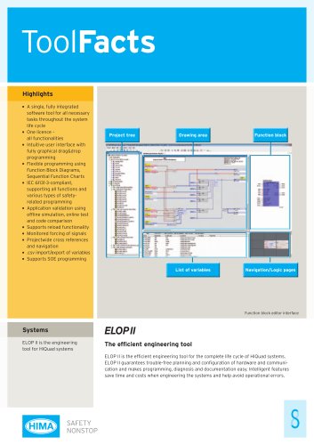 ToolFacts ELOP 2
2 Pages
 SystemFacts Planar4
2 Pages
 Brochure HIMatrix general
6 Pages
 F8627X/F8628X
2 Pages
 Four new CPUs
2 Pages
 SystemFacts_HIQuad
2 Pages
 HIQuad
16 Pages
 HIMax®
20 Pages


