
- Catalogs
- Hidracar, S.A.
- BDOS Technical Catalogue


- Company
- Products
- Catalogs
- News & Trends
- Exhibitions
BDOS Technical Catalogue

BDOS Technical Catalogue
HIDRACAR S.A. is a company with over 40 years of experience in designing and manufacturing hydro-pneumatic accumulators and pulsation dampeners. Their products comply with CE regulations, are insured for civil liability, and the company holds ISO 9001 certification and ASME 'U' authorization for pressure vessel manufacturing.
HIDRACAR's accumulators are rigorously tested at 1.5 times their maximum design pressure and feature CNC lathe precision machining. They have a computerized manufacturing registry for traceability, and the charging gas valve maintains its seal up to 700 bar.
Pulsation dampeners stabilize flow in hydraulic circuits with dosing or volumetric pumps. They contain pressurized gas, typically nitrogen, and use a separator element to prevent gas leaks. The separator material is chosen based on circuit characteristics like pressure, temperature, and corrosiveness.
The dampener divides the pump's output, storing part of it and releasing it back into the circuit during the pump's suction phase to maintain stable flow and pressure.
The size of the dampener depends on the volume of liquid it must store and the circuit's minimum and maximum pressures. The ideal gas law is used for calculations, considering factors like residual pulsation and temperature variations.
To prevent wear on the separator element, the dampener should not be completely emptied in each cycle. The charging gas pressure should be set at 0.8 times the minimum circuit pressure.
Pulsation dampeners are beneficial for piston pumps, which exhibit significant flow variations. Graphs illustrate the flow characteristics of these pump types.
Formulas are provided for calculating the volume stored by the dampener based on the number of pistons in a pump. The document emphasizes setting acceptable pressure limits as a percentage of the working pressure.
For maximum efficiency, the dampener should be mounted in-line with the pump outlet, with minimal distance between the pump and dampener.
Figures illustrate proper installation of a discharge pulsation damper, with in-line mounting preferred for higher efficiency.
Specific applications, such as circuits requiring periodic cleaning and those with variable working pressure, are addressed with recommendations for quick dismantling systems and volume calculations.
Proper installation and sizing of pulsation dampeners are crucial for maintaining efficient and stable hydraulic circuits.
Cavitation occurs when static pressure at the pump inlet is low. Pulsation dampeners help maintain constant liquid velocity and pressure, reducing cavitation risk.
They are essential for volumetric or dosing pumps to prevent pressure drops that could lead to cavitation.
The dampener at the suction should be approximately twice the size of the one at the discharge and installed close to the pump inlet.
Dampeners with separators are more effective but require larger sizes and costs. Calculations for dampener volumes with and without separators are provided.
Installing a dampener at the discharge prevents pressure fluctuations, reducing material fatigue and vibrations.
For single-effect dosing pumps, avoiding pressure fluctuations is crucial to prevent circuit breakdowns.
Instructions are provided for filling and adjusting the dampener to ensure proper operation.
HIDRACAR's in-line pulsation dampers are suitable for various processes and feature no limitation on nitrogen gas charging pressure and effective cleaning design.
The reference code includes details such as type, volume, gas charging valve type, design pressure, separator material, and more.
Various adapters and optional pressure gauges and connection hoses for different pressure ranges are offered.
Catalog excerpts

HIDRACAR ACCUMULATOR OR PULSATION DAMPENER, YOU GET: • More than 40 years of experience in designing, manufacturing and applying hydro-pneumatic accumulators. • A pressure apparatus that meets the CE regulations. • The machining precision of CNC lathes. • Safety: ♦ All our accumulators undergo hydraulic tests at 1.5 times its maximum design pressure. ♦ Civil liability insurance coverage (CATALANA OCCIDENT Cía. de Seguros). • Quality control: ♦ We have the ISO 9001 certification. ♦ We have the Certificate of Authorization of ASME “U” ♦ Computerised manufacturing registry control that makes possible...
Open the catalog to page 3
The named company is authorized by the American Society of Mechanical Engineers (ASME) for the scope of activity shown below in accordance with the applicable rules of the ASME Boiler and Pressure Vessel Code. The use of the certification mark and the authority granted by this Certificate of Authorization are subject to the provisions of the agreement set forth in the application. Any construction stamped with this certification mark shall have been built strictly in accordance with the provisions of the ASME Boiler and Pressure Vessel Code. HIDRACAR Pol. lnd. Bufalvent G/Ramon Farguell no 73...
Open the catalog to page 5
SOME TECHNICAL AND PRACTICAL RECOMMENDATIONS ABOUT PULSATION DAMPENERS IN CIRCUITS WITH DOSING OR VOLUMETRIC PUMPS DESCRIPTION OF A PULSATION DAMPENER AND HOW IT WORKS A pulsation dampener is a vessel with pressurized gas inside, normally nitrogen. The initial filling or inflating gas pressure inside the dampener must always be lower than the pressure of the circuit where it is installed. The inflating gas pressure of the dampener will be called “P0”. In all pulsation dampeners there is a separator element to isolate the gas from the circuit liquid; its main function being to avoid gas leaks....
Open the catalog to page 6
2 When δV gets introduced into the dampener the gas contained inside will be compressed and, therefore, its volume reduced and the pressure increased. The final gas volume (V2) will be the initial gas volume minus the volume of liquid introduced (δV). The initial gas volume is the total volume of the dampener or the size of the dampener. The size of the dampener is an unknown value to be calculated in every case depending on the kind of pump. This volume or size of the dampener will be called “V0” From all this, we can establish that: Every dampener has a constant derived from its size and its...
Open the catalog to page 7
3 At the initial gas charge pressure value “P0” there is no liquid inside the dampener and the gas fills the whole dampener interior. The curve cuts the ordinate axis in that point where the pressure value is “Po”. In the abscissa axis is represented the volume of liquid introduced into the dampener in each working cycle. The pressure “P1” is the gas pressure when a volume “v” has been introduced into the dampener. The pressure “P2” is the value reached by the gas when the additional volume “δV” is introduced into the dampener. From the curve in Figure 2 we can deduce that for a fixed dampener...
Open the catalog to page 8
4 With all this known data: δV, P1 and P2, we can already calculate the dampener size “V0”. The ideal gas law in isothermal conditions (Boyle’s law) (later on we will clarify this equation for this application) gives us the following equality: Finally, from (1) and (2) we obtain: and then from (1), (2), (3) and (4) we will get: From the underlined ends of the equalities we obtain the final formula: This is the simplified theoretical formula to calculate the pulsation dampener volume as a function of δV, P1 and P2. As we have already said, it is accepted as a norm that the charging gas pressure,...
Open the catalog to page 9
5 If we divide the above formulas (5.1 for Isotherm curve) divided by (6.1 for Adiabatic curve), we obtain a relation K which is function of the residual pulsation ϴ. For low values of admissible residual pulsations (below +-5%), the value obtained is practically constant (K=0,8). So, we will incorporate the factor K in the formula (5), to take in consideration the adiabatic expansion and compression of the gas inside the dampener: P2 x δV V0 = ---------------------------0.8 x 0.8 x (P2 - P1) This formula can be used in practice for nearly all industrial applications. It will be very unlikely...
Open the catalog to page 10
6 The curves in Figure 4 let us see how a pulsation dampener works: If we pay attention to the first curve (on the top), representing a single piston pump, we can observe that for this type of pump the use of a dampener is almost essential, as otherwise during half revolution of the pump crankshaft no liquid flow is delivered. Also if the pump does not include a dampener, the diameter of the pipe must be calculated for the maximum instantaneous flow, which takes place when the piston speed is also at its maximum, in the middle of piston stroke (the flow curve is a sinusoid). With a dampener installed...
Open the catalog to page 11
7 Before all, let’s consider that for the mean flow (M.F. in the graph) corresponds the working pressure “Pt”. When the pump is in its impulsion cycle and the instantaneous flow increases and achieves the point 1 in the graph of the Figure 5, the dampener starts to store liquid (see in the top graph which represents the instantaneous flow delivered by the pump and the lower graph where the pressure variability with the use of a dampener is represented). The dampener ought to be charged at the adequate inflating pressure (80% of the working pressure). In the point 1 the damper starts to store...
Open the catalog to page 12
Figure 6. Scheme for the proper installation of a discharge pulsation damper in the pump outlet. 1.- The dampener must be mounted with its axis aligned with the axis of the pump outlet. 2.- The distance between the pump outlet port and the dampener port connection must be as short as possible. 3.- The pipe section between the pump and the dampener connection must be calculated for the pump maximum instantaneous flow. 4.- The remaining pipe section of the circuit must be calculated for the mean flow. In the scheme of Figure 7 we will see more clearly all the concepts we have exposed so far. ω...
Open the catalog to page 13All Hidracar, S.A. catalogs and technical brochures
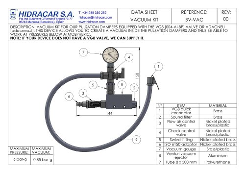 VACUUM KIT
1 Page
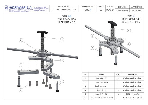 Bladder Dismantling Tool
1 Page
 Selection Guide
12 Pages
 Dismantling kit
1 Page
 Anti-corrosion valve
1 Page
 Temperature fuse
1 Page


Archived catalogs

- Vessel
- Cylinder
- Storage vessel
- Hydraulic cylinder
- Pneumatic cylinder
- Industrial tank container
- Spring
- Single-acting cylinder
- Piston cylinder
- Industrial cylinder
- Compact cylinder
- Hydraulic absorber
- Shock buffer
- Mechanical buffer
- Crane scale
- Industrial buffer
- Compression spring
- Pressure tank
- Threaded adapter
- Stainless steel cylinder