- Catalogs
- HepcoMotion
- PRT2 No.1 Design Criteria for Track System Drives
- Company
- Products
- Catalogs
- News & Trends
- Exhibitions
PRT2 No.1 Design Criteria for Track System Drives
1 /9Pages

PRT2 No.1 Design Criteria for Track System Drives
1 /9Pages
Catalog excerpts
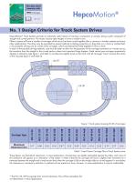
Precision Ring and Track System This data sheet interacts with No. 1 Design Criteria for Track System Drives HepcoMotion® Track Systems provide an extremely useful means of moving a component or process along a path composed of straight and curved portions. The tracks may be open lengths or form a closed circuit. Often a system will have a number of carriages which are to be driven round together (this is common in transfer systems and many other applications). The drive may be provided by several methods including projections or drag links on a chain or toothed belt, or by positively driving one (or more) of the carriages, which are themselves linked together to form a chain. In each of the possible driving methods, care must be taken to allow for the geometry of the carriage movement as it travels across the transition from the straight to the curved section where two important things happen; Fixed centre type carriages momentarily develop a clearance (see figure 1 and table 1) and become slightly loose on the track; and all carriages ‘move’ towards the centre of the ring (see figure 2 and table 2). Lift Off Carriage Type Figure 1 Track system showing lift off of carriages Maximum Clearance/mm Table 1 Fixed Centre Carriage Play at Track System Joints These figures are theoretical clearances. In most applications, the bearings are slightly preloaded against the slides, and some of this clearance will appear as a ‘relaxation’ of the system. In these instances the carriage will have a slightly freer movement as it traverses between the straight and curved section than when the carriage is fully on the straight slide or curved segment. In most duties the clearance or momentary reduction in preload will not present an issue, however, in some applications it may be undesirable. * The FCC 25 159 has greater than normal clearance. This will be noticeable, but not detrimental in many appli
Open the catalog to page 1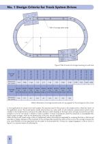
No. 1 Design Criteria for Track System Drives Path of carriage plate centre Carriage Type Figure 2 Path of centre of carriage traversing an oval track Movement into centre Carriage Type Movement into centre Table 2 Movement of carriage towards centre of ring segment as the carriage turns the corner In most applications for closed circuit track systems, the important area for the process is the straight section, where the ‘action’ of the application occurs. The curved section usually only functions as a return path. In such instances, precise motion control is only needed on the straight sections...
Open the catalog to page 2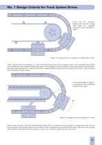
No. 1 Design Criteria for Track System Drives Ensure that the connection between the belt and carriage plate allows for movement towards the centre identified in Table 2. Figure 3 Carriages driven via a spigot on a toothed belt or chain When using this type of arrangement, it is usual to have the driving force on the carriage off centre, and consequently there will be some contribution to the moment loading of the system. Such loading must be accounted for when calculating the load and life of the system (see datasheet No. 3 Load life information). Alternatively the carriage may be connected...
Open the catalog to page 3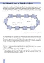
No. 1 Design Criteria for Track System Drives In systems which use carriages linked by tie bars to form a carriage train, there is a tendency for the apparent length of the train to change as the carriages traverse the joint between straight and curved sections. The link between any pair of carriages cut a chord across the ring segment centre line, which lengthens the carriage train. At the same time the ends of the links move to a larger effective radius, due to being mounted outboard of the bearing assemblies, which has the effect of shortening the carriage train. The combination of these 2...
Open the catalog to page 4
No. 1 Design Criteria for Track System Drives If expansion and contraction of the carriage train may be a problem in an application, then it will be advisable to estimate the amount of length change in the system. Table 3 below gives typical figures for the length change associated with a single joint from straight to curve. Track system curve diameter Link Length Link centre on carriage Approximate expansion/Contraction per track joint Carriage System Table 3 Approximate expansion and contraction of carriage trains. The information contained in Table 3 can be used to calculate the approximate...
Open the catalog to page 5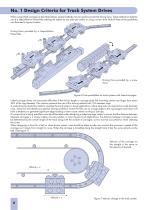
No. 1 Design Criteria for Track System Drives When using linked carriages as described above, several methods may be used to provide the driving force. These methods include the use of a HepcoMotion Powerslide indexing the system by one pitch per stroke, or using a screw drive. Both of these drive possibilities are illustrated in figure 6 below. Driving force provided by a HepcoMotion Powerslide. Driving force provided by a screw drive. Figure 6 Drive possibilities for track systems with linked carriages. Linked carriage drives can encounter difficulties if the tie bar length or carriage plate...
Open the catalog to page 6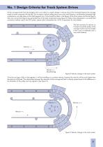
No. 1 Design Criteria for Track System Drives As the carriage travels from the straight to the curve, there is a rapid change in velocity due to the increased distance the carriage needs to travel compared with the belt. This increase in velocity takes place over a very small distance, and therefore extremely high accelerations can take place at the slide/segment joint. Care should be taken in the design of the drive system and the belt lugs to take into account the large forces generated due to the high accelerations (see figure 8). Hepco have developed a successful belt connection method used...
Open the catalog to page 7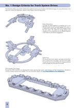
No. 1 Design Criteria for Track System Drives The illustrations below give details of alternative methods of driving track systems with linked carriages. For more information or for help with a particular application, please contact Hepco’s technical department. Pocket Wheel Drive Carriages are linked together by connecting rods. A cam follower located on each carriage engages with cutouts in a pocket drive wheel which moves the carriages around the track system. This method of driving requires some compliance in the connecting rods and sufficient clearance in the wheel for cam follower engagement....
Open the catalog to page 8All HepcoMotion catalogs and technical brochures
 HLG Hepco Linear Ball Guides
17 Pages
 SBD Sealed Belt Drive
11 Pages
 MFS machine fencing system
6 Pages
 HGS gantry solutions
9 Pages
 HDS2 Heavy Duty Slide System
27 Pages
 DTS2 Dynamic Track Systems
8 Pages
 PRT2 No. 2 Installation Details
10 Pages
 PRT2 No.8 DTS Components
19 Pages
 PRT2 No. 11 Mix & Match
3 Pages
 PRT2 1-Trak
8 Pages
 Floating Bearings
2 Pages
 DualVee Wash Down Wheels
2 Pages
 MCS Catalogue
36 Pages
 Profiles with Linear Guides
8 Pages
 ALR Aluminium Rings
4 Pages
 HTS Drawer Slides Catalogue
40 Pages
 MHD Catalogue
8 Pages
 PSD80 No.1 Ballscrew
6 Pages
 HDRT Heavy Duty Ring and Tracks
13 Pages
 Uni-Guide – Product Overview
4 Pages
 ZIMM GSZ & Z Series Screw Jacks
196 Pages


Archived catalogs
 PRT2 No.6 Bleed Lubrication
8 Pages
 ZIMM – Z Series Leaflet
4 Pages
 MCS – RapiLok
2 Pages
 DualVee Guide Wheels Catalogue
11 Pages
 DualVee Technical Data Guide
12 Pages
 SL2 Stainless Steel Slide System
15 Pages
 BSP Ballscrew Premier
9 Pages


- Actuator
- Linear actuator
- Electric actuator
- Profile
- Metal profile
- Compact actuator
- Screw actuator
- Workbench
- Linear motion system
- Aluminum profile
- Plain bearing
- Precision actuator
- Extruded aluminum actuator
- Pneumatic actuator
- Ball screw actuator
- Double-acting actuator
- Stainless steel actuator
- Stepper actuator
- Positioning actuator
- Ball bearing slide