- Catalogs
- HepcoMotion
- PRT2 No. 2 Installation Details
- Company
- Products
- Catalogs
- News & Trends
- Exhibitions
PRT2 No. 2 Installation Details
1 /10Pages

PRT2 No. 2 Installation Details
1 /10Pages
Catalog excerpts

Precision Ring and Track System This data sheet interacts with No. 2 Installation Details HepcoMotion precision ring and track systems are manufactured to high quality standards and provides smooth and accurate motion for any application. The supporting structure for mounting these systems is somewhat instrumental in achieving overall accuracy and efficiency, consequently the mounting/datum faces should be machined flat and parallel. When choosing a fixing method, consideration should be given to both the application and the components being used. The following datasheet outlines various mounting and assembly options. Details of component and assembly dimensions can be found on pages 22 to 53 of the PRT2 catalogue. Unless the ‘Pre-drillable’ option is requested HepcoMotion® Track Systems will require manual drilling and setting to ensure they are installed correctly and to the accuracy required. The following instructions are intended to aid the installation process. Caution Sharp Edges - Track systems are required to have sharp edges on the ends to ensure joint quality when butted together. 7 9 8 Part Complete track system Part Description Track System Straight Slide 180° Track Ring Segment Fixed Centre Carriage Plate Eccentric Bearing Concentric Bearing Blanking plug Jacking Screw
Open the catalog to page 1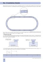
No. 2 Installation Details Before beginning to fit the track system in place it is advisable to position it as it will look when assembled. This will confirm that all the parts are correct before it is assembled and will also check that the marks on each side of the joint correspond, as shown below. Track system laid out in position before securing Note: To ensure ease of assembly, make sure that the two track system straight slides are parallel to each other and the ends are aligned, if they are not, the track system will not fit together correctly. 1. Setting the first slide. 1.1 To ensure...
Open the catalog to page 2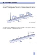
No. 2 Installation Details 2. Securing the first slide 2.1 To ensure that the slides are fixed correctly, hold tight against the register/ dowel pins and secure using clamps, as shown in figure 2.1, the track can then be used as a template to spot through into the base. The slide can be removed and the holes drilled to suit, this will avoid possible misalignment from the cumulative effect of hole position tolerances and ensure that the slide is parallel. Figure 2.1 Clamping arrangement 2.2 Once the holes have been drilled the slides can be secured to the base. Start from the middle of the slide...
Open the catalog to page 3
No. 2 Installation Details for Track Systems 3. Setting second and subsequent slides 3.1 Second and subsequent slides should be assembled at the correct pitch line to ensure that the segment will fit into place. This should be taken into account when machining the register or dowel pin holes. Machined Register PCD of ring Figure 3.1 Slides fitted at correct PCD 3.2 If securing the slides with dowel pins as location it is best to fix one of the slides whilst leaving the other ‘floating’, assemble two carriage plates to a suitably sized joining plate and place onto the slides (figure 3.2). Run...
Open the catalog to page 4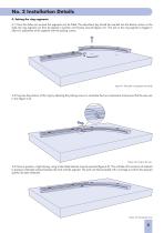
No. 2 Installation Details 4. Setting the ring segments 4.1 Once the slides are secured the segments can be fitted. The adjustment key should be inserted into the bottom recess on the slide, the ring segment can then be placed in position and loosely secured (figure 4.1). The slot on the ring segment is bigger to allow for adjustment of the segment with the jacking screws. Figure 4.1 Fitting the ring segment to the slide 4.2 Fine-tune the position of the ring by adjusting the jacking screws to centralise the two components and ensure that the vees are in line (figure 4.2). Figure 4.2 Lining up...
Open the catalog to page 5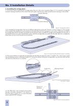
No. 2 Installation Details 5. Assembling the carriage plates 5.1 Ensure that, before assembling the carriages plates, they are in the correct orientation (figure 5.1). For standard carriages the concentric bearings should be on the inside of the track system with the more widely spaced eccentric bearings on the outside. Eccentric Bearings Concentric Bearings Figure 5.1 Carriage plate orientation 5.2 To assemble the carriage plates, there are two different methods that can be used. The first is as shown in figure 5.2, the carriages will be supplied fully adjusted and can be pushed onto the slide...
Open the catalog to page 6
No. 2 Installation Details Pre-Drillable Track Systems Pre-drillable track systems are available on request. This means that the holes for the track system are able to be drilled prior to the track system arriving. When placing an order for a pre-drillable track system please ensure that the requirement is clearly stated at the end of the order as shown in the example below. Pre-drillable track system Type P required. Once an order has been received a custom drawing will be created which will give the position of the holes and their tolerances. The drawing will be sent to confirm the details...
Open the catalog to page 7
No. 2 Installation Details Rings can be used as the fixed or rotating elements within a system. Within a fixed system, the rings should be mounted to a machined register and bolted securely. For maximum flexibility the rings slides are supplied with both internal and external register faces, either can be used depending upon the application. Mounting holes should be drilled and tapped at the appropriate size on the ring PCD, this can be achieved by accurately pre-drilling the holes prior to assembly or “spotting through” the ring holes. For less demanding applications the ring can be secured...
Open the catalog to page 8
No. 2 Installation Details Where the ring is the rotating element, the position of the supporting bearings is the important factor. It is recommended that two concentric bearings should be placed 120º apart in order to provide a datum reference, the other bearings should be of eccentric type. All eccentric bearings can be used where positional adjustment of the ring is required. Where access is restricted to the underside of the mounting face, blind hole bearings should be used. Blind hole eccentric bearings are supplied with a mounting plate which allows adjustment of the bearing from above,...
Open the catalog to page 9All HepcoMotion catalogs and technical brochures
 HLG Hepco Linear Ball Guides
17 Pages
 SBD Sealed Belt Drive
11 Pages
 MFS machine fencing system
6 Pages
 HGS gantry solutions
9 Pages
 HDS2 Heavy Duty Slide System
27 Pages
 DTS2 Dynamic Track Systems
8 Pages
 PRT2 No.8 DTS Components
19 Pages
 PRT2 No. 11 Mix & Match
3 Pages
 PRT2 1-Trak
8 Pages
 Floating Bearings
2 Pages
 DualVee Wash Down Wheels
2 Pages
 MCS Catalogue
36 Pages
 Profiles with Linear Guides
8 Pages
 ALR Aluminium Rings
4 Pages
 HTS Drawer Slides Catalogue
40 Pages
 MHD Catalogue
8 Pages
 PSD80 No.1 Ballscrew
6 Pages
 HDRT Heavy Duty Ring and Tracks
13 Pages
 Uni-Guide – Product Overview
4 Pages
 ZIMM GSZ & Z Series Screw Jacks
196 Pages


Archived catalogs
 PRT2 No.6 Bleed Lubrication
8 Pages
 ZIMM – Z Series Leaflet
4 Pages
 MCS – RapiLok
2 Pages
 DualVee Guide Wheels Catalogue
11 Pages
 DualVee Technical Data Guide
12 Pages
 SL2 Stainless Steel Slide System
15 Pages
 BSP Ballscrew Premier
9 Pages


- Actuator
- Linear actuator
- Electric actuator
- Profile
- Metal profile
- Compact actuator
- Screw actuator
- Workbench
- Linear motion system
- Aluminum profile
- Plain bearing
- Precision actuator
- Extruded aluminum actuator
- Pneumatic actuator
- Metal workbench
- Ball screw actuator
- Double-acting actuator
- Stainless steel actuator
- Stepper actuator
- Ball bearing slide