- Catalogs
- Helmholz GmbH & Co. KG
- DP/CAN Coupler
DP/CAN Coupler
1 /31Pages
DP/CAN Coupler
1 /31Pages
Catalog excerpts
DP/CAN Coupler PROFIBUS DP for CAN-Bus Coupler for CAN Layer 2 700-651-CAN01 Manual Edition 8 / 23.07.2012 HW1 & FW 1.51 and higher Order number of manual: 900-651-CAN01/en Systeme Helmholz GmbH | Hannberger Weg 2 | D-91091 Großenseebach Phone: +49 9135 7380-0 | Fax: +49 9135 7380-110 l E-mail: [email protected] | Internet: com
Open the catalog to page 1
All rights are reserved, including those of translation, reprinting, and reproduction of this manual, or parts thereof. No part of this manual may be reproduced, processed, copied, or transmitted in any way whatsoever (photocopy, microfilm, or other method) without the express written permission of Systeme Helmholz GmbH, not even for use as training material, or using electronic systems. All rights reserved in the case of a patent grant or registration of a utility model or design. Copyright © 2012 by Systeme Helmholz GmbH Hannberger Weg 2, 91091 Grossenseebach, Germany Note: We have checked...
Open the catalog to page 3
Revision history of this document: Edition Revision Notice about consistent data extended GSD filename of the 29Bit object corrected and further small corrections DIP-Switch table edited
Open the catalog to page 4
DP/CAN Coupler Safety Information Vertical and horizontal mounting System Overview Application and function description Items supplied Installing and parameterizing the device Defining the I/O address area in the PLC Consistent data Maximum parameter sizes and address ranges Parameterizing transmit and receive messages Parameterizing the Receive Object 11-bit protocol 29-bit protocol Data exchange Handshake bits Transmit and receive objects Receive Object 11-bit protocol
Open the catalog to page 5
29-bit protocol Receive Object Service Transmit Object 11-bit protocol 29-bit protocol Technical Data Further documentation DP/CAN Coupler
Open the catalog to page 6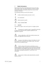
Safety Information Please observe the safety information given for your own and other people's safety. The safety information indicates possible hazards and provides information about how you can avoid hazardous situations. The following symbols are used in this manual. Caution, indicates hazards and sources of error Gives information Hazard, general or specific Danger of electric shock The DP/CAN coupler is only used as part of a complete system. The operator of a machine system is responsible for observing all safety and accident prevention regulations applicable to the application in question....
Open the catalog to page 7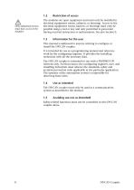
Only authorized persons must have access to the modules! The modules are open equipment and must only be installed in electrical equipment rooms, cabinets, or housings. Access to the electrical equipment rooms, barriers, or housings must only be possible using a tool or key and only permitted to personnel having received instruction or authorization. See also Section 0. This manual is addressed to anyone wishing to configure or install the DP/CAN coupler. It is intended for use as a programming manual and reference work by the configuring engineer. It provides the installing technician with all...
Open the catalog to page 8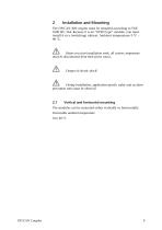
The DP/CAN 300 coupler must be installed according to VDE 0100 IEC 364. Because it is an “OPEN type” module, you must install it in a (switching) cabinet. Ambient temperature: 0 ºC – 60 ºC. Before you start installation work, all system components must be disconnected from their power source. Danger of electric shock! During installation, application-specific safety and accident prevention rules must be observed. Vertical and horizontal mounting The modules can be mounted either vertically or horizontally. Permissible ambient temperature: 0 to 60 ºC DP/CAN Coup
Open the catalog to page 9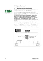
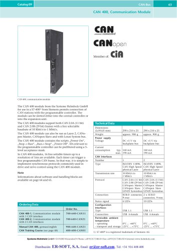
System Overview Application and function description The DP/CAN coupler from System Helmholz GmbH allows you to connect any CAN stations to the PROFIBUS DP. The DP/CAN coupler must be parameterized as a PROFIBUS station in the Hardware Configurator. The necessary GSD files are supplied with the device. The PROFIBUS side is configured as a DP slave. The interfaces meet EN 50170 and are electrically isolated. The baud rate of 9.6kBaud to 12Mbaud is detected automatically. The size of the input and output information does not exceed 312 bytes. The CAN bus interface meets ISO/DIN 11898-2 and is electrically...
Open the catalog to page 10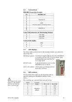
PROFIBUS DP Data line B GND VP (power supply for terminating resistors) 3-way CAN connector (no terminating resistor): CAN High CAN-GND CAN-Low The three LEDs on the front of the module inform you about its operating state. LED Power (green): Continuous light indicates that the PROFIBUS is running and the PLC is in run mode. Slow blinking indicates that the PLC is in stop mode. LED DP (red): A parameterization error on the PROFIBUS has occurred. LED CAN (yellow): CAN frames are being received from the CAN bus. The 8-switch DIP switch on the housing front is used for setting the PROFIBUS address...
Open the catalog to page 11
Items supplied DP/CAN Coupler Layer 2 incl. 2 x 3-pin connector for CAN bus and 24V power supply CD with GSD files and instructions Manual, German/English CAN bus plug connector 700-690-0BA11 CAN bus plug connector with cable connector CAN bus plug connector with axial cable outlet DP/CAN Coupler
Open the catalog to page 12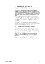
In Layer 2 mode the DP/CAN coupler can transmit and receive any CAN messages (CAN 2.0A/B, 11-bit and 29-bit). A distinction is made between two different transmission methods. In the first method, the identifier and size of the CAN message is permanently parameterized in the transmit and receive objects and only the data are transmitted via the PROFIBUS. Each transmit and receive object therefore corresponds to one CAN frame. In the second method the Receive Object can receive several messages filtered by a parameterizable acceptance mask. In this method not only the data but also the identifier...
Open the catalog to page 13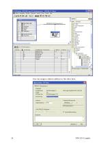
You can assign a station address to the slave here. DP/CAN Coupler
Open the catalog to page 14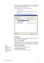
The DP/CAN coupler is supplied with the necessary information with the parameterization frame from the master on start-up about the CAN frames to be processed. The following CAN parameters are defined here: Cyclic transmission time of the Transmit Object (if required) Number of receive and transmit messages CAN baud rate: Possible baud rates: 1 Mbps, 500 Kbps, 250 Kbps, 125 Kbps, 100 Kbps, 50 Kbps, 20 Kbps, 10 Kbps Timer for Transmit Object: You can set a time (10 ms to 1000 ms) for cyclic transmission of the Transmit Object here. If you select the option “Deactivated” the Transmit Object is...
Open the catalog to page 15All Helmholz GmbH & Co. KG catalogs and technical brochures
 REX 200, Ethernet Router
2 Pages
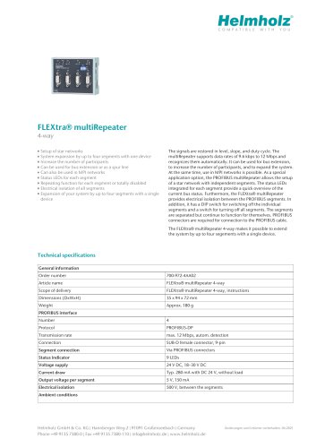
 FLEXtra® multiRepeater
6 Pages
 FLEXtra® multiRepeater
2 Pages
 DP/CAN Coupler
1 Page
 CAN-Bridge
2 Pages
 CAN 300 PRO
2 Pages


Archived catalogs
 PROFINET product overview
6 Pages
 PN/PN Coupler
2 Pages
 REX 100 Ethernet router
2 Pages
 FLEXtra® profiPoint
2 Pages
 700-840-16S01
2 Pages
 700-840-8ES01
2 Pages
 700-840-5ES01
2 Pages
 Power module DC 24 V
2 Pages
 PROFINET IO
2 Pages
 PROFIBUS-DP
2 Pages
 CANopen Slave
2 Pages
 DeviceNet Slave
2 Pages
 Modbus/TCP
2 Pages
 EtherNet/IP
2 Pages
 EtherCAT
2 Pages
 DI 2x DC 24 V
2 Pages
 DI 4x DC 24 V
2 Pages
 5-port, unmanaged
2 Pages
 8-port, unmanaged
2 Pages
 4-Port, managed
2 Pages
 8-Port, managed
2 Pages
 16-port, unmanaged
2 Pages


- Electrical cable
- Data connector
- Ethernet switch
- SARRALLE management software
- SARRALLE automation software
- Industrial network switch
- SARRALLE analysis software
- Digital I/O
- SARRALLE process software
- IO module
- Managed switch
- Screw-in connector
- Industrial connector
- Gigabit ethernet switch
- Rectangular connector
- Analog I/O
- DIN rail mounted network switch
- RJ45 network switch
- Waterproof network switch