
Catalog excerpts
DP/CAN Coupler PROFIBUS DP to CAN-Bus Coupler for CANopen® and CAN Layer 2 700-650-CAN01 Manual Edition 7 / 03.12.2012 HW1 & FW 1.29 and higher Manual order number: 900-650-CAN01/en Systeme Helmholz GmbH | Hannberger Weg 2 | D-91091 GroRenseebach Phone +49 91 35 7380-0 | Fax +49 91 35 7380-110 | info@helmholz.de | www.helmholz.com
Open the catalog to page 1
All rights are reserved, including those of translation, reprinting, and reproduction of this manual, or parts thereof. No part of this manual may be reproduced, processed, copied, or transmitted in any way whatsoever (photocopy, microfilm, or other method) without the express written permission of Systeme Helmholz GmbH, not even for use as training material, or using electronic systems. All rights reserved in the case of a patent grant or registration of a utility model or design. Copyright © 2012 by Systeme Helmholz GmbH Hannberger Weg 2, 91091 Grossenseebach, Germany Note: We have...
Open the catalog to page 3
Revision history of this document: Edition Revision Correction of the number of pages (page 14) Heartbeat at CANopen® (FW. 1.29) Extended information on consistent data Additional information for the start-up procedure Heartbeat protocol from slave is supported and Some corrections GSD filename of CANopen corrected and further small corrections DIP switch table edited
Open the catalog to page 4
2.1 Vertical and horizontal mounting 9 3.1 Application and function description 10 4 Configuration (CANopen® Master) 13 4.1 Install and parametrize the device 13 4.2 Defining the I/O address area in the PLC 16 4.4 Maximum parameter sizes and address ranges 17 5 Programming (CANopen® Master) 19 5.2 CAN network start-up procedure 19 5.4 Receiving emergency frames 21 5.4.1 Emergency receive mailbox 21 5.4.2 Handshaking for emergency frames 21 5.5 Parameterizing CAN modules (SDO transfer) 22 5.5.1 Expedited SDO transfers (up to 4 bytes of data) 22 DP/CAN Coupler
Open the catalog to page 5
5.5.3 Handshaking SDOtx (transmit SDO) 24 5.5.4 Handshaking SDOrx (receive SDO) 24 6.1 Installing and parameterizing the device 25 6.2 Defining the I/O address area in the PLC 28 6.4 Maximum parameter sizes and address ranges 29 6.5 Parameterizing transmit and receive messages 29 6.6 Parameterizing the variable receive object 30 7.3 Receive and transmit objects 32 7.4 Variable receive object 33 7.5 Variable transmit object 34 7.6 Cyclically transmitting of the transmit object 34 DP/CAN Coupler
Open the catalog to page 6
Safety Information Please observe the safety information given for your own and other people's safety. The safety information indicates possible hazards and provides information about how you can avoid hazardous situations. The following symbols are used in this manual. Caution, indicates hazards and sources of error gives information hazard, general or specific danger of electric shock The DP/CAN coupler is only used as part of a complete system. The operator of a machine system is responsible for observing all safety and accident prevention regulations applicable to the application in...
Open the catalog to page 7
Restriction of access A Only authorized persons must have access to the modules! The modules are open equipment and must only be installed in electrical equipment rooms, cabinets, or housings. Access to the electrical equipment rooms, barriers, or housings must only be possible using a tool or key and only permitted to personnel having received instruction or authorization. See also Chapter 1.5. 1.3 Information for the user This manual is addressed to anyone wishing to configure or install the DP/CAN coupler. It is intended for use as a programming manual and reference work by the...
Open the catalog to page 8
The DP/CAN coupler must be installed according to VDE 0100 IEC 364. Because it is an “OPEN type” module, you must install it in a (switching) cabinet. Ambient temperature: 0 ºC – 60 ºC. Before you start installation work, all system components must be disconnected from their power source. Danger of electric shock! During installation, application-specific safety and accident prevention rules must be observed. Vertical and horizontal mounting The modules can be mounted either vertically or horizontally. Permissible ambient temperature: 0 to 60 ºC DP/CAN Coup
Open the catalog to page 9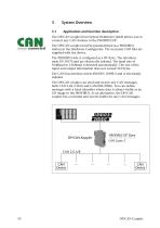
3.1 Application and function description The DP/CAN coupler from System Helmholz GmbH allows you to connect any CAN stations to the PROFIBUS DP. The DP/CAN coupler must be parameterized as a PROFIBUS station in the Hardware Configurator. The necessary GSD files are supplied with the device. The PROFIBUS side is configured as a DP slave. The interfaces meet EN 50170 and are electrically isolated. The baud rate of 9.6kBaud to 12Mbaud is detected automatically. The maximum volume of input and output information is 312 bytes. Die CANopen® side is configured as an independent master that can be...
Open the catalog to page 10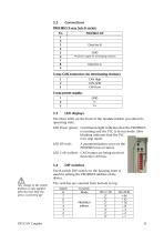
Changing the DIP switches is only effecting after power on! 3.2 Connections PROFIBUS 9-way Sub-D socket: DP/CAN Coupler
Open the catalog to page 11
3.5 Scope of supply DP/CAN Coupler 700-650-CAN01 incl. 2 x 3-pin connector for CAN bus and 24V power supply CD with GSD file examples and instructions 3.6 Accessories Manual, German/English CAN bus plug connector CAN bus plug connector with cable connector CAN bus connector axial DP/CAN Coupler
Open the catalog to page 12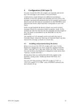
Configuration (CANopen Master) The DP/CAN coupler allows you to convert data from a PROFIBUS DP circuit to a CAN circuit and vice versa. Before data can be exchanged between the PROFIBUS and the CAN bus, the start-up phase of the PROFIBUS of the DP/CAN coupler must be parameterized. This is done automatically by the PROFIBUS master (PLC) when the bus starts up. The configuration of the CANopen® bus (baud rate, number of nodes, distribution of PDOs) must be stored as a PROFIBUS node in the parameter set of the DP/CAN coupler when the DP/CAN coupler is defined. When parameterization is...
Open the catalog to page 13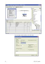
You can now drag and drop the “DP/CAN-Koppler CO V2M” onto a PROFIBUS network you have already set up. Then assign a suitable station address to the slave. DP/CAN Couple
Open the catalog to page 14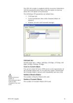
The DP/CAN coupler is supplied with the necessary information about the structure of the CANopen® bus from the master via the parameterization frame during start-up. The following CAN parameters are defined here: ■ CAN baud rate ■ Transmission time for the SYNC frame ■ Number of used CANopen® nodes in the CAN circuit A The number of CAN modules must match the number of defined "NEW MODULE------" entries! Possible baud rates: 1 Mbps, 500 Kbps, 250 Kbps, 125 Kbps, 100 Kbps, 50 Kbps, 20 Kbps, 10 Kbps Sync time: The transmission time of a Sync frame (COB-ID: 80) on the CAN bus is set here. (10...
Open the catalog to page 15All Helmholz GmbH & Co. KG catalogs and technical brochures
-
 CAN-Bridge
2 Pages
-
 CAN 300 PRO
2 Pages
-
 PN/PN Coupler
2 Pages
-
 DP/CAN Coupler
2 Pages
-
 without PG
2 Pages
-
 FLEXtra® multiRepeater4-way
2 Pages
-
 REX 200, Ethernet router
2 Pages
-
 REX 100 Ethernet router
2 Pages
-
 Modbus master-slave driver
1 Pages
-
 CAN 400
2 Pages
-
 PROFINET product overview
6 Pages


Archived catalogs
-
 16-port, unmanaged
2 Pages
-
 8-Port, managed
2 Pages
-
 4-Port, managed
2 Pages
-
 8-port, unmanaged
2 Pages
-
 5-port, unmanaged
2 Pages
-
 DI 4x DC 24 V
2 Pages
-
 DI 2x DC 24 V
2 Pages
-
 EtherCAT
2 Pages
-
 EtherNet/IP
2 Pages
-
 Modbus/TCP
2 Pages
-
 DeviceNet Slave
2 Pages
-
 CANopen Slave
2 Pages
-
 PROFIBUS-DP
2 Pages
-
 PROFINET IO
2 Pages
-
 Power module DC 24 V
2 Pages
-
 700-840-5ES01
2 Pages
-
 700-840-8ES01
2 Pages
-
 700-840-16S01
2 Pages
-
 FLEXtra® profiPoint
2 Pages