TGA
1 /172Pages

TGA
1 /172Pages
Catalog excerpts

Fans for technical building services (TGA) and smoke extraction. Helios Ventilatoren Helios Ventilation Systems Ltd. • 5 Crown Gate • Wyncolls Road • Severalls Industrial Park • Colchester, Essex CO4 9HZ phone: +44 - (0) 1206 228 500 • telefax: +44 - (0) 1206 228 501 • e-mail: [email protected] • www.heliosfans.co.uk Copyright ©: Helios Ventilatoren, 78056 Villingen-Schwenningen, Germany. Certified according to ISO 9001/2008. We reserve the rights for alterations without prior notice. Document no. 86 979.840/ 09.13
Open the catalog to page 1
Helios code index 2 Dimensioning of ventilation systems 3 General information to heat and smoke removal systems (RWA) 9 Medium pressure axial fan 44 incl. mounting packages for two-stage Z- and parallel P-units RADAX®-High pressure in-line mixed-flow fan 72 incl. mounting packages for two-stage Z- and parallel P-units Smoke protection pressure- and stairway scavenging air systems 108 - Smoke protection pressure systems RDA 112 - Stairway scavenging air systems TSA 114 Smoke and heat exhaust fans as roof-mounted, in-line rectangular or centrifugal fans 130 - BDV, Roof-mounted smoke exhaust fans...
Open the catalog to page 3
Helios code index AMD Medium pressure axial fans Gas warning systems – analog – digital Medium pressure smoke exhaust axial fans, F300, F400 Temperature sensor for outside (for EUR 6 C) Full motor protection switch 147 Mounting feet Transformer controller with motor protection unit, 1 ph. Parallel operation of two identical fans Pole switches for Dahlander windings PGWA / PGWU Pole switches for pole changing fan Reverse and pole switches Retangular counter flange Frequency inverter Mounting package, 2-stage unit 8, 44 on, 72 on Full motor protection switch 165 Counter flange Mounting package,...
Open the catalog to page 4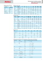
Dimensioning of ventilation systems Basic factors of SI-System I Basic factors of SI-System to DIN EN 1301 Physical value Einheit Name Short I Air flow volume units Unit symbol Name of unit symbol Electric current Luminous intensity I Pressure units Unit symbol Name of unit symbol millimetre water column techn. atmosphere physic. atmosphere millimetre mercury column pound-force per square inch pound-force per square foot inch mercury column inch water colume I Energy units Units I Important physical values and their relationship to the basic factors of the SI-System Physical value Short symbol...
Open the catalog to page 5
Dimensioning of ventilation systems Calculation of required air flow volume The required extract air or intake air volume of a room depends on the use and the contamination or odours that are created within it. A critical factor may also be the amount of heat that needs to be extracted. I Calculation of intake air flow volume per person (DIN EN 13779, as of 09.2007) I Calculation of air flow volume using the number of people (DIN EN 15251, as of 08.2007) The calculation of the air flow volume may be done using various criteria with the following equations and tables. In some cases, several ways...
Open the catalog to page 6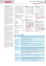
Dimensioning of ventilation systems Acoustics The noise level of a fan must be taken into consideration when designing a ventilation system. The affect of a sound source (fan) on the rooms that need ventilation and the neighbourhood can be estimated using the following information: The noise is primarily created by the fan, possibly also by ducting, and other components like filters, heaters, shutters etc. If the air flow speed is too high this will result in whistling noises. A maximum air flow speed of 6 m/s is recommended and at the same time noise transmission by fan or other components must...
Open the catalog to page 7
Dimensioning of ventilation systems Fan laws and performances curves Fan performance units . Air flow volume V [m3/h, m3/s] Total pressure Dptotal = Dpstat. + pdyn. [Pa] Static pressure Dpstat. = Dptotal - pdyn. [Pa] Dynamic pressurepdyn. = r/2·c2 [Pa] Shaft power Pw [W, kW] Nominal motor power P [W, kW] Sound power/pressure level LwA, LpA, [dB(A)] Calculation of the required shaft power of a fan . V · Dptot Pw1 = [kW] 1000 · h Dptot = Total pressure increase [Pa] h = Efficiency of the fan . V = Air flow volume in [m3/s] When using a pole-switching motor Stalling area Pole figure Performance...
Open the catalog to page 8
Dimensioning of ventilation systems Two-stage fan connections Two-stage operation with Z-unit I General Two-stage means, that two identical high-pressure fans which are arranged one behind the other operate in-line in a joint duct system. In this case the static pressure of both fans add up at constant air flow rate. · V = const. Dpfa = pfa1+ pfa2 I Operating modes (Fig. 11) For simultaneous operation of both fans the performances corresponds to curve Dpfa1 + Dpfa2. For individual operation of one fan the performance curve is reduced to curve Dpfa1 or curve Dpfa2. Via partial load control, use...
Open the catalog to page 9
Dimensioning of ventilation systems Pressure losses Ventilation systems consist of va- rious different components like: fan, bends, grilles, heat exchan- All these components have a resi- stance which needs to be conside- pressure loss Apstat (static pressu- re) of the total system is calculated by adding all individual resistances Figure 5 Pressure losses in a ventilation system - Shaped sections (bends, T-pieces) © - Other components (filters, heaters, grilles) © -ilter unit ^ain repellent- Pressure drop in circular or rectangular ducting AP/L1;2...: from table in figure 6 [Pa/m Correction...
Open the catalog to page 10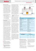
General information to smoke and heat exhaust systems (RWA) I General information Smoke exhaust systems have the task to garantee a smoke-free layer above the ground in the event of a fire.This should ensure visibility, enabling the evacuation of humans and animals, as well as an active fire-fighting by the fire department.In addition, emergency signs must be recogized also in panic.The creation of smoke-free areas reduces the risk of inhalation of toxic fire gases and the associated threat to life and limb. The temperature in the smoke-free layer should not exceed 70 °C. According to DIN 18232...
Open the catalog to page 11All Helios Ventilation catalogs and technical brochures
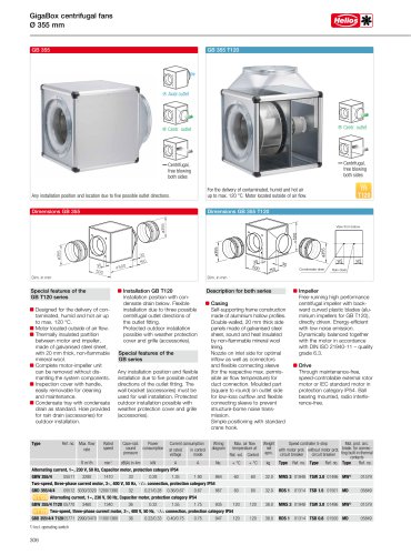 GigaBox centrifugal fans
2 Pages
 Triple M1 MiniVent Family
16 Pages
 KWL Generation
65 Pages
 General catalog
414 Pages
Archived catalogs
 HECO Ventilation System
4 Pages
 ultraSilence Family
14 Pages
 Supply Air Handling Units
4 Pages
 SlimVent
4 Pages
 RenoPipe
8 Pages
 EC greenVent
84 Pages
 MegaBox centrifugal fan
12 Pages
 Roof fans
22 Pages
 The circular duct solutions
22 Pages
 Helios air treatment
10 Pages
 Axial Fans
30 Pages


