


MIM
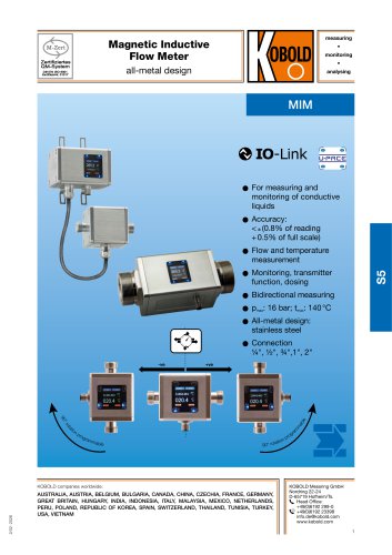
MIM
- Accuracy: Less than ±0.8% of reading plus 0.5% of full scale.
- Pressure and Temperature: Maximum pressure of 16 bar and maximum temperature of 140°C.
- Material: All-metal design with stainless steel construction.
- Connection Sizes: Available in ¼", ½", ¾", 1", and 2".
- Flow and temperature measurement capabilities.
- Bidirectional measuring and monitoring functions.
- Universal Precision and Control Electronics (U-PACE) with configurable outputs.
- Coloured TFT display, rotatable in 90° steps.
- Drinking water approval and compliance with food contact regulations.
- Measurement Process: Electromagnetic, requiring a minimum conductivity of ≥20 µS/cm.
- Response Time: Less than 100 ms for alarm/pulse/frequency output and less than 1 second for analogue output.
- Temperature Sensor: PT1000 with accuracy ≤±2°C.
- Protection: IP67 rated, suitable for various environmental conditions.
- Supply Voltage: 19 - 30 VDC with a maximum power consumption of 200 mA.
- Outputs: Configurable for pulse, frequency, alarm, and analogue signals.
- Communication: Supports IO-Link and KofiCom modes.
- Mounting: Can be installed in any direction with various connection fittings available.
- Accessories: Includes wall mounting kits and various adapter sets for different connection types.
- Various fitting sets are listed with their respective process connections, types, dimensions, and weights. For example, the ZUB-AD2G20N20 is an adapter with a G ¾ female to ¾" NPT female connection, weighing 359 g.
- All fitting kits include sealing gaskets or O-rings, specifically 2 x Klinger SIL® flat sealing gaskets or 2 x FKM O-rings for the ZUB-AD2G50T50 model.
- The flow meter is designed in an all-metal construction and is available in both compact and remote versions.
- Dimensions are provided for both versions, with and without wall mounting brackets.
- The device features configurable measuring modes and display layouts, including 'Single' and 'Dual' configurations.
- Display configurations include options for flow rate, volume, temperature, and part volume, with color-coded fonts indicating measurement status (white for within full scale, yellow for 100% full scale to overflow, and red for overflow).
- Output configurations include switching, analogue, and pulse outputs, with assignments to flow, temperature, and part volume.
- The document includes a disclaimer stating no responsibility for errors and that specifications are subject to change without notice.
Catalog excerpts
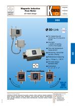
Magnetic Inductive Flow Meter all-metal design or measuring and F monitoring of conductive liquids Accuracy: < ± (0.8% of reading + 0.5% of full scale) Monitoring, transmitter function, dosing Bidirectional measuring All-metal design: stainless steel KOBOLD companies worldwide: AUSTRALIA, AUSTRIA, BELGIUM, BULGARIA, CANADA, CHINA, CZECHIA, FRANCE, GERMANY, GREAT BRITAIN, HUNGARY, INDIA, INDONESIA, ITALY, MALAYSIA, MEXICO, NETHERLANDS, PERU, POLAND, Republic of Korea, SPAIN, SWITZERLAND, THAILAND, TUNISIA, turkey, USA, VIETNAM KOBOLD Messring GmbH Nordring 22-24 D-65719 Hofheim/Ts. Head Office: +49(0)6192 299-0 +49(0)6192 23398 [email protected] www.kobo
Open the catalog to page 1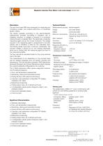
Magnetic Inductive Flow Meter in all-metal design Model MIM electromagnetic see order details conductive fluids >20 pS/cm (>35 pS/cm for measuring range 01H/01G) <±(0.8 % of reading + 0.5 % of full scale)* ±0.2 % of full scale Mounting position In-/outlet: Pressure drop: Operation: Description The new flow meter MIM was developed for measuring and monitoring smaller- and medium-sized flow of conductive liquids in pipes. The device operates according to the electromagnetic measurement principle. According to Faraday's Law of magnetic induction, a voltage is induced in a conductor moving through...
Open the catalog to page 2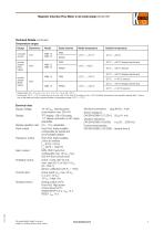
Magnetic Inductive Flow Meter in all-metal design Model MIM Technical Details (continued) Temperature ranges 2) Continuous -20 °C ... +70 °C, short-term up to max. +85 °C (for max. 60 minutes at max. +40 °C ambient temperature and repetition earliest after 4 hours). Use of the electrical outputs remains limited to temperature range -20 °C ... +70 °C. Electrical connection: plug M12x1,4-pin Shock resistance Environmental testing Supply voltage: 19 - 30 VDC, internal power consumption max. 200 mA Display: TFT display, 128 x 128 pixels, 1.4" display orientation in 90° steps adjustable Display repetition...
Open the catalog to page 3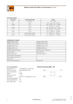
Magnetic Inductive Flow Meter in all-metal design Model MIM Connection/ranges lO-Link specification Manufacturer ID: Manufacturer name: lO-Link specification: Bitrate: Minimal cycle time: SIO-Mode: Block parameterisation: Operational readiness: Max. cable length: Kobold Messring GmbH No responsibility taken for errors; subject to change without prior notice.
Open the catalog to page 4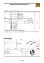
Magnetic Inductive Flow Meter in all-metal design Model MIMOrder Details (Example: MIM-12 15H G5 C3T 0)Model MIM-12 = housing/ electrode VA, FKM seal MIM-134) = housing/ electrode VA, EPDM seal U-PACE Electronics Special version C3T = compact, TFT display, 2 outputs (current/voltage/ pulse/frequency/alarm output configurable), M12x1 plug P023) = remote version, TFT display, 2 m PVC cable, max. 85 °C E023) = remote version, TFT display, K5)= including calibration report 11 l/min-package (nameplate (l/min or ml/min, °C, bar)), calibrated range and temperature °C 2) GPM-package (nameplate (GPM or...
Open the catalog to page 5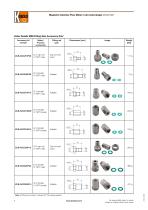
Magnetic Inductive Flow Meter in all-metal design Model MIM Order Details MIM Fitting Sets Accessory Kits* * Note: All fitting kits include 2 x Klinger SIL® flat49sealing gaskets SW 36 No responsibility taken for errors; subject to change without prior notice. Meter / Process connection
Open the catalog to page 6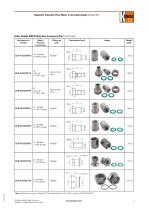
Magnetic Inductive Flow Meter in all-metal design Model MIM 49 * Note: All fitting kits include 2 x Klinger SIL® flat sealing gaskets or 2 x FKM O-rings (for ZUB-AD2G50T50) No responsibility taken for errors; subject to change without prior notice. Meter / Process connection SW 36 SW 32 Order Details MIM Fitting Sets Accessory Kits* (continued)
Open the catalog to page 7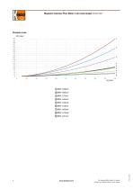
Magnetic Inductive Flow Meter in all-metal design Model MIM © MIM-1x40xx9 No responsibility taken for errors; subject to change without prior notice.
Open the catalog to page 8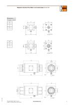
Magnetic Inductive Flow Meter in all-metal design Model MIM Dimensions [mm] Compact version G No responsibility taken for errors; subject to change without prior notice.
Open the catalog to page 9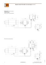
Magnetic Inductive Flow Meter in all-metal design Model MIM Dimensions [mm] (continued) Remote version Without wall mounting brackets With wall mounting brackets No responsibility taken for errors; subject to change without prior notice.
Open the catalog to page 10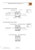
OUT1 configured as 4-20 mA and assigned to flow Configurable variables Display area for output status Font white: MV* within FS Font yellow: 100% FS <= MV* <= OvFlow Measuring variable with sign for direction 4 digits + decimal point Unit for measuring variable INFO Key symbol 1 Key symbol 2 (Menu functions) (Options INFO) * Measured Value OUT1 configured as switching output Push-Pull and assigned flow OUT2 configured as analogue output Configurable variables 4-20 mA and assigned to temperature for both displays Font white: MV within FS Font yellow: 100% FS <= MV <= OvFlow INFO Flow rate Volume...
Open the catalog to page 11All Heinrichs Messtechnik GmbH catalogs and technical brochures
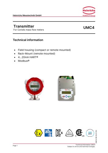 UMC4
6 Pages
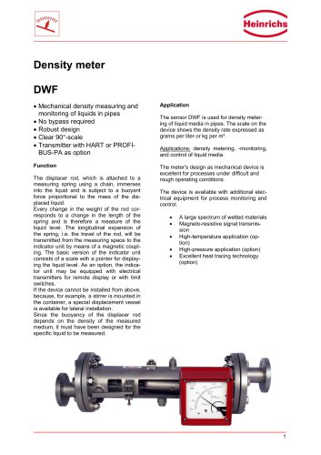 DWF
4 Pages
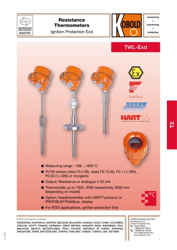 TWL-Exd
14 Pages
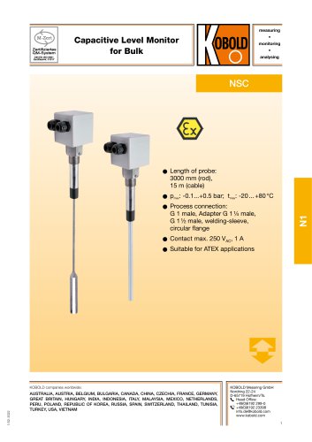 NSC
4 Pages
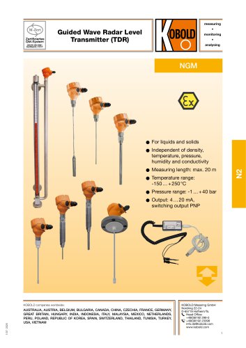 NGM
10 Pages
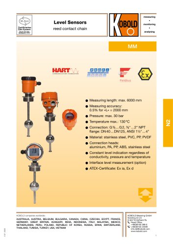 MM
13 Pages
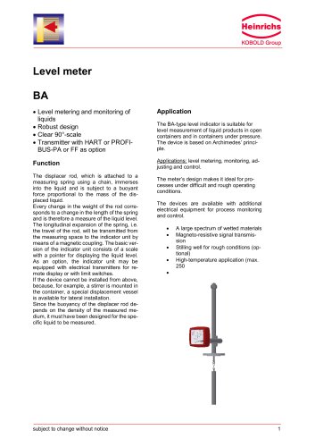 BA
7 Pages
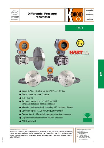 PAD
24 Pages
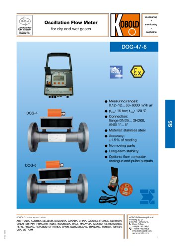 DOG-4 / -6
14 Pages
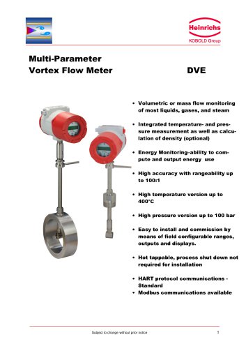 DVE
8 Pages
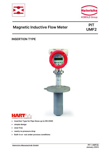 PIT UMF2
5 Pages
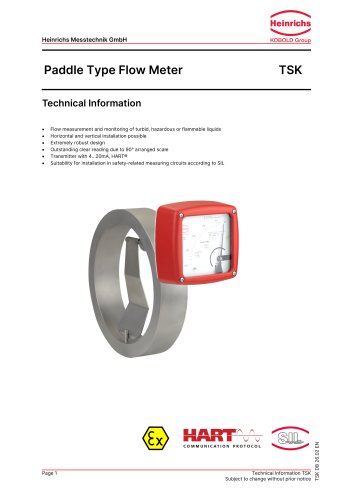 Paddle Type Flow Meter
11 Pages
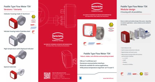 TSK
2 Pages
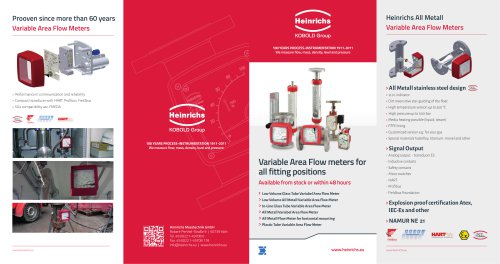 Variable Area Flow Meters
2 Pages
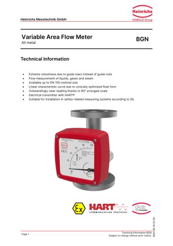 BGN
12 Pages
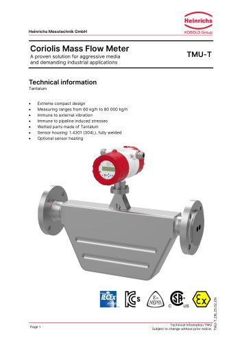 TMU-T
6 Pages
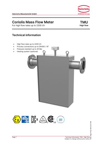 TMU High flow
7 Pages
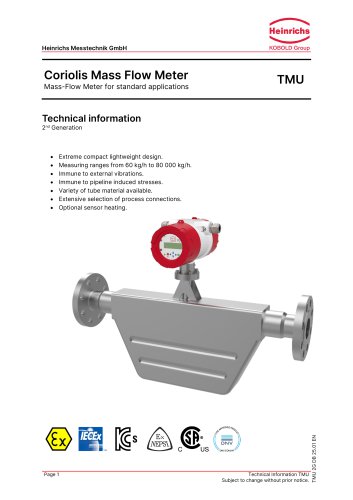 TMU
7 Pages
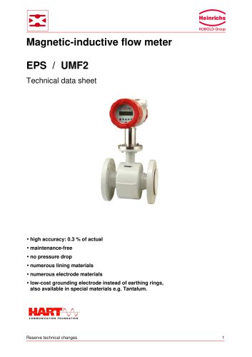 Magnetic-inductive flow meter
18 Pages
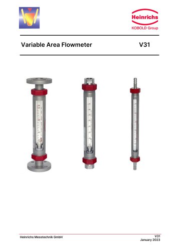 Variable Area Flowmeter
14 Pages
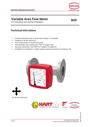 Variable Area Flow Meter
12 Pages
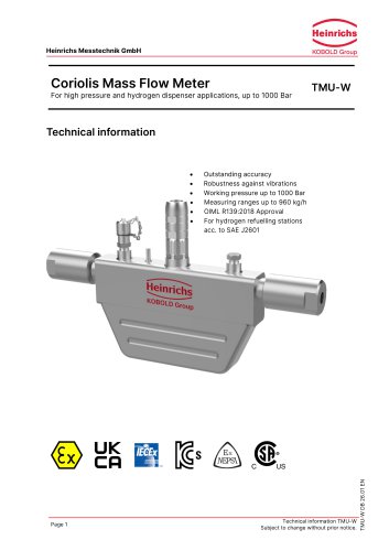 Coriolis Mass Flow Meter
6 Pages
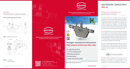 TMu - W
2 Pages
- Liquid flow monitor
- Resistance temperature sensor
- Pressure transmitter
- Level limit switch
- Analog pressure transmitter
- Liquid level detector
- Waterproof flow meter
- Gas flow monitor
- Level probe
- Stainless steel flow monitor
- Liquid level sensor
- Industrial flow monitor
- Waterproof pressure transmitter
- Precision flow meter
- Stainless steel pressure transmitter
- Waterproof temperature sensor
- In-line flow meter
- Pt100 temperature transducer