
- Catalogs
- Heinrichs Messtechnik GmbH
- Magnetic-inductive flow meter


Magnetic-inductive flow meter
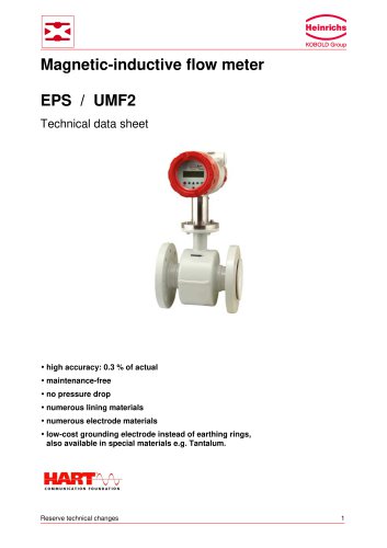
Magnetic-inductive flow meter
The document outlines the technical specifications and operational details of the EPS/UMF2 magnetic-inductive flow meter, emphasizing its high accuracy, maintenance-free operation, and absence of pressure drop. It is suitable for various conductive liquids and offers multiple material options for linings and electrodes.
The flow meter operates on Faraday's law of induction, where a conductive medium flowing through a magnetic field induces a voltage proportional to the flow velocity. This voltage is converted into a standardized electrical signal by a transmitter. The EPS sensor can be paired with the UMF2 transmitter, which can be mounted compactly or remotely.
The EPS sensor is designed for measuring the volume flow of liquids, slurries, and pastes without pressure drop. It is unaffected by pressure, temperature, density, or viscosity but should avoid solid particles and gas bubbles. It is suitable for harsh environments with various lining and electrode materials available.
- Nominal Sizes: 2 to 1200 mm
- Process Connections: Flanges, food connections, and others on request
- Lining Materials: Hard-rubber, Soft-rubber, PTFE, Ceramics, EPDM
- Electrode Materials: Hastelloy C276, stainless steel, Titanium, Tantalum, Platinum-Rhodium
- Pressure Ratings: Up to PN 40 (580 psi)
- Temperature Range: -20°C to +150°C depending on lining material
- Conductivity: >= 5 µS/cm
- Accuracy: ± 0.3% of measured value
- Protection: IP67, IP68 on request
The document includes a detailed table of flow rates for various diameters, indicating minimum and maximum flow capacities in liters per second and cubic meters per hour.
Recommendations include avoiding vacuum conditions, ensuring proper mounting to prevent vibrations, and not installing downstream of a valve. Proper thermal insulation is advised to prevent heat transfer to the transmitter.
- Mounting: Compact or remote
- Power Supply: 115/230 VAC or 24 VDC
- Output: 0/4-20 mA HART®, pulse output
- Protection: IP68
- Communication: HART®
Guidelines for grounding and electrical connections are provided, emphasizing the importance of proper grounding for both metallic and non-metallic pipelines.
The document concludes with a detailed model code description, outlining various configurations based on material, lining, electrodes, and process temperature.
1. Flange and Connection Types: The document lists various flange and connection types including DIN, ANSI, and JIS standards. These are specified with different diameters (DN) and pressure ratings (PN).
2. Material Options: Materials for process connections include stainless steel, Hastelloy, Tantalum, Platinum/Iridium, and Titanium. Each material is suited for specific linings such as PTFE, ceramic, or rubber.
3. Transmitter Mounting and Protection: Options for transmitter mounting include integrated and remote transmitters with protection classes IP67 and IP68. Remote transmitters come with additional terminal connection boxes.
4. Certificates: Compliance certificates available include Certificate of Compliance with Order 2.1, Test Report 2.2, and Inspection/Material Certificates 3.1 and 3.2 according to DIN/EN 10204:2008.
5. Power Supply and Output: Power supply options include 230V AC, 115V AC, and 24V DC. Output signals are available as 0/4-20 mA with HART protocol.
1. Installation: The document provides guidelines for installing transmitters with specific cable lengths and junction box requirements.
2. Material Selection: Recommendations are given for selecting materials based on the type of lining and application requirements.
1. Flange Standards: The document references standards such as DIN EN 1092-1 and ASME B16.5 for flange specifications.
2. Certificates: Compliance with DIN/EN 10204:2008 for material and inspection certificates.
1. Design and Model Codes: The document includes design codes for Heinrichs and Kobold models.
2. Special Requests: Options for special requests are available for materials and configurations not covered in standard offerings.
Heinrichs Messtechnik GmbH, Robert-Perthel-Straße 9, D-50739 Köln, Germany. Contact via phone at +49-221-49708-0 or email at [email protected].
Catalog excerpts
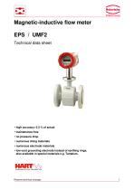
Magnetic-inductive flow meter EPS / UMF2Technical data sheet • high accuracy: 0.3 % of actual • numerous lining materials • numerous electrode materials • low-cost grounding electrode instead of earthing rings, also available in special materials e.g. Tantalum. Reserve technical changes
Open the catalog to page 1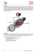
Function An electrically conductive medium flowing through an orientated magnetic field in accordance to Faraday's law of induction will induce a voltage proportional to the mean flow velocity rate and hence the volumetric flow. A magnetic inductive flowmeter consist of an isolated lined tube, through which a conductive liquid flows, a magnetic field coil and two electrodes. The electrode voltage is detected by a transmitter and converted into standardized electrical signal such as 4-20 mA or pulses. The sensor EPS can be used in combination with the Heinrichs Messtechnik UMF2 transmitter. The...
Open the catalog to page 2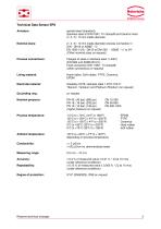
Nominal sizes: Process connections: Lining material: Electrode material: Grounding ring: Nominal pressure: Process temperature: Ambient temperature: Measuring range: painted steel (standard), stainless steel at DIN11851; Tri-Clamp® and Ceramic lined 2 / 3 / 6 / 10 mm inside diameter 2 / 3 / 6 / 10 mm inside diameter process connection in DIN - DN10 or ASME - %“ EN 1092-1/JIS - DN15 to DN1200 - ASME - %“ to 24“ (Other nominal sizes on request) Flanges of steel or stainless steel (1.4301) Food connection DIN 11851, Tri-Clamp® (other connections on request) Hard-rubber, Soft-rubber, PTFE, Ceramics,...
Open the catalog to page 3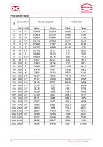
4 Reserve technical changes
Open the catalog to page 4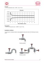
Accuracy +/- 0,3 % of measured value + 0,0001 * (Q at 10 m/s) To avoid vacuum, emptying of pipes or gas aggregation please take notice of the following mounting advice Reserve technical changes
Open the catalog to page 5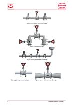
Upstream of pump, vacuum possible Mount in ascending main Do not mount downstream of a valve Use support to prevent vibrations Pipe narrowing with maximum 8° angle Reserve technical changes
Open the catalog to page 6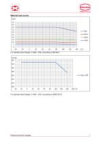
For stainless steel flanges (1.4404 / 316L) according to EN1092-1 For stainless steel flanges (1.4404 / 316L) according to ASME B16.5 Reserve technical changes
Open the catalog to page 7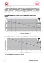
Ambient conditions As the sensors are an element of the pipe, these are normally thermally isolated when installed to save energy and prevent accidental physical contact. The heat of the process temperature will be transferred through the supports neck of the compact mounted transmitter or the terminal box. For this reason the thermal insulation of the sensor should only extend half way up the support of the transmitter. It is essential not to include the transmitter or the terminal box into the thermal insulation. The maximum permissible fluid temperature range is stated on the rating plate...
Open the catalog to page 8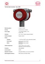
Technical data transmitter: Type UMF2 Mounting options: die cast Aluminum, painted Power supply: LCD, 2-lines, 16 digits, background lighted Interface language: English, German Output: Analogue: 1 x 0/4-20 mA HART®, active, galvanically isolated Pulse output: passive, galvanically isolated 24V, 60mA passive, galvanically isolated 24V, 60mA Status: Ambient temperature: -20°C to +60°C (-4°F to +140°F), depending on process temperature Diagnostic functions: Empty pipe detection, coil current surveillance Electromagnetic tolerance: Reserve technical changes
Open the catalog to page 9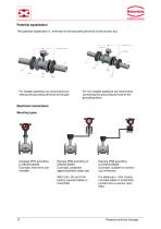
Potential equalization The potential equalization is achieved via the grounding terminal of the junction box. For metallic pipelines we recommend con- For non-metallic pipelines we recommend necting the grounding terminal to the pipe. connecting the grounding terminal to the grounding discs. Mounting types Compact IP67 according to DIN/EN 60529 Dust tight, short time submersible. Remote IP65 according to DIN/EN 60529 Dust tight, protected against powerful water jets. With 2.5m, 5m and 10m factory mounted cable on transmitter Remote IP68 according to DIN/EN 60529 Dust tight, suitable for continuous...
Open the catalog to page 10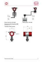
Remote version up to 10m cable Remote version >10m cable Dimensions of the Transmitter UMF2 (All measures in mm) Transmitter compact mounted Reserve technical changes
Open the catalog to page 11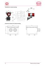
Transmitter for remote mounting Junction box (sensor) for remote mounting Reserve technical changes
Open the catalog to page 12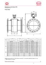
Dimensions of the Sensor EPS (All measures in mm) (standard -pressure level) Weights are proximate (for PN16) without transmitter. For transmitter additional weight of 2.4 kg (* higher pressure on request) Reserve technical changes 13
Open the catalog to page 13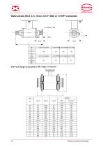
Wafer-version DN 2, 3, 6, 10 incl. G1/2" (ISO) or 1/2"NPT connection DN 14 Reserve technical changes
Open the catalog to page 14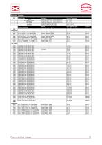
Model code Description Reserve technical changes 15
Open the catalog to page 15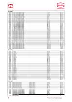
ANSI flanges XXXX special on request xx xx 16 Reserve technical changes
Open the catalog to page 16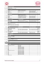
Reserve technical changes 17
Open the catalog to page 17
Subject to change.Heinrichs Messtechnik GmbH Postfach 600260 Robert-Perthel-StraSe 9 18 Reserve technical changes
Open the catalog to page 18All Heinrichs Messtechnik GmbH catalogs and technical brochures
 Variable Area Flowmeter
14 Pages
 Variable Area Flow Meter
12 Pages
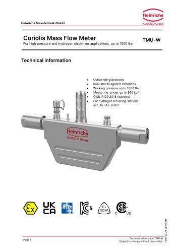 Coriolis Mass Flow Meter
6 Pages
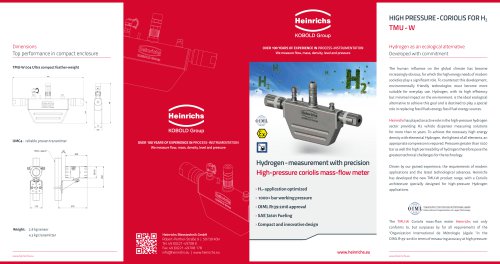 TMu - W
2 Pages
- Temperature probe
- Liquid flow monitor
- Resistance temperature sensor
- Pressure transmitter
- Level limit switch
- Analog pressure transmitter
- Liquid level detector
- Waterproof flow meter
- Gas flow monitor
- Level probe
- Stainless steel flow monitor
- Liquid level sensor
- Industrial flow monitor
- Waterproof pressure transmitter
- Precision flow meter
- Stainless steel pressure transmitter
- Waterproof temperature sensor
- In-line flow meter
- Pt100 temperature transducer