 Website:
Heidrive GmbH
Group: Allied Motion Technologies Inc.
Catalog excerpts
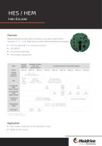
Features: Magnetoresistive encoder series consisting of four basic versions with a resolution of 10 - 12 bit. Depending on model following interfaces are available: • sin/cos output with 1 VPP period per revolution • SSI, BiSS C • Incremental signals ABZ • Commutation signals UVW Absolute encoders single-turn sin/cos 1 period / revolution SSI Absolute encoders multi-turn, battery-backed HEM1-001 Incremental and/or commutation signals HES2-001 diff., 1.0 Vpp (only with braid wire X2) SSI diff., gray coded, 12 bit ST SSI single ended, gray coded, 12 bit ST (only with connector X1) Incremental ABZ (line numbers) Commutation UVW (pole number) single ended 4 pole * braid wire X2 (standard), Connector X1 upon request Temperature range Comment - 30 °C to + 125 °C with braid wire X2 - 30 °C to + 105 °C with connector X1 without battery with battery * 2- and 8- pole upon request ** other pole numbers upon request Application: • Rotor position detection for EC and BLDC motors • Digital position sensor BiSS diff., binary coded, 20 bit MT + 12 bit ST Connection options diff. (256) diff. 6 pole **
Open the catalog to page 1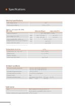
Electrical specifications ESD-voltage (all pins) Power supply voltage VCC Digital in- and outputs SSI / BiSS, ABZ, UVW Maximum frequency * Input voltage CLK+, CLKOutput voltage DATA+, DATA-, A+, A-,B+, B-, Z+, Z-, U+, U-, V+, V-, W+, W- Output current (per output) * can be lower depending on the connection requirements. Amplitude sin+, sin-, cos+, cos- Reference level Periods / revolution Output current (per output) Ambient conditions Permitted operating temperature - 30 °C to 105 °C with connector X1 - 30 °C to 125 °C with braid wire X2 Permitted storage temperature Permitted relative air...
Open the catalog to page 2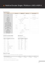
Heidrive Encoder Single-/ Multiturn 1 (HES 1/HEM 1) Upon request gray / binary BiSS diff. sin/cos differential Power supply voltage Current consumption (typ., without load) With 120 Ohm load and SSI Data With maximum load Standby power Standby current * Upon request Connector X1 (upon request) Error (Open Collector) Encoder reset Preset multi-turn Battery TLH-2450 Calculations consisting of informations from battery manufacturer Ambient temperature Life at 100 % battery operation * * battery operation = encoder power supply is switched off Further information for your application on reque
Open the catalog to page 3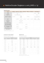
Heidrive Encoder Singleturn 2 und 3 (HES 2 / 3) Specifications Variant Upon request SSI single ended (only with connector X1) BiSS binary Power supply voltage Current consumption (typ., without load) With maximum load Alternative settings upon request * at HES3 are optional output signals possible Connector X1 (upon request) X2.9 to X2.14 only HES3 equiped Braid wire approx. 200 mm long (not stripped)
Open the catalog to page 4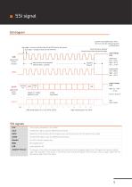
SSI diagram positive counting direction: from the front onto the AS bearing plate (without gear) neg. edge -> time to read the state of the DATA line by the master pos. edge -> change of state on the DATA line more CLK pulses allowed timouet starts after last positive edge input voltage level determiation of the adaptive timeout (first 1.5 pulses) adaptive timeout single ended (CLK - GND): high: > 2.0 V low: < 0.8 V DATA (generated by the slave) Singleturn: 12 Bbit Multiturn: 0 Bit output voltage level Coding: Gray coded differential signals: CLK, /CLK, DATA, /DATA single ended signals:...
Open the catalog to page 5
BiSS signal BiSS diagram positive counting direction: from the front onto the AS bearing plate (without gear) neg. edge -> time to read the state of the DATA line by the master pos. edge -> change of state on the DATA line more pulses allowed timout starts after last positive edge /CDM determination of the adaptive timeout (first 1.5 pulses) (DATA) Singleturn: 12 Bit Multiturn: 20 Bit Coding: binary coded single ended (CLK - GND): high: > 2.0 V low: < 0.8 V output voltage level input voltage level differential signals: MA, NMA, SLO, NSLO single ended signals: MA, SLO 45 Bits 48 total length...
Open the catalog to page 6
ABZ diagram positive counting direction: from the front onto the AS bearing plate (without gear) edge accuracy output voltage level high: Vcc - 0.8 V to Vcc low: 0 V to 0.8 V line angle UVW diagram positive counting direction: from the front onto the AS bearing plate (without gear) output voltage level high: Vcc - 0,8 V to Vcc low: 0 V to 0,8 V mechanical angle P: number of pole pairs 4 P+1 (number of poles /
Open the catalog to page 7
Technical data subject to change! Last changes: 04/2022 Heidrive GmbH Starenstraße 23 93309 Kelheim Tel. 09441/707-0 Fax 09441/707-259 info@heidrive.de www.heidrive.com
Open the catalog to page 8All Heidrive GmbH catalogs and technical brochures
-
HMD Next Generation servo drives
112 Pages
-
Motion&sysystem
28 Pages
-
heidrive-product
24 Pages
-
Servo drives
44 Pages
-
HMP - Servo drive systems
60 Pages
-
EC / BLDC Motors
36 Pages
-
Motor programs
28 Pages
-
Image brochure
8 Pages
-
Flat gear type F105
12 Pages
-
Gear motors compact
4 Pages
-
One cable solution
6 Pages
-
SIL encoders
2 Pages


