- Catalogs
- Heidrive GmbH
- HES/HEM Hall Encoder
HES/HEM Hall Encoder
1 /8Pages
HES/HEM Hall Encoder
1 /8Pages
Catalog excerpts

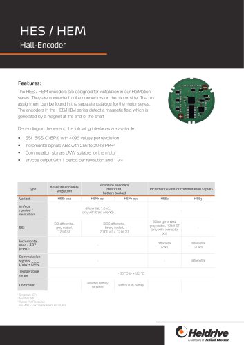
Features: The HES / HEM encoders are designed for installation in our HeiMotion series. They are connected to the connectors on the motor side. The pin assignment can be found in the separate catalogs for the motor series. The encoders in the HES/HEM series detect a magnetic field which is generated by a magnet at the end of the shaft Depending on the variant, the following interfaces are available: • SSI, BiSS C (BP3) with 4096 values per revolution • Incremental signals ABZ with 256 to 2048 PPR3 • Commutation signals UVW suitable for the motor • sin/cos output with 1 period per revolution and 1 Vpp Absolute encoders singleturn Absolute encoders multiturn, battery backed Incremental and/or commutation signals sin/cos 1 period / revolution differential, 1.0 Vpp (only with braid wire X2) SSI differential, gray coded, 12 bit ST BiSS differential, binary coded, SSI single ended, gray coded, 12 bit ST (only with connector X1) external battery required with built-in battery €)HekUve A Company of AliiedMotion
Open the catalog to page 1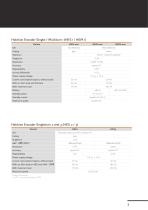
sin/cos differential Power supply voltage Current consumption (typical, without load) With 120 Ohm load and SSI Data With maximum load Battery Standby power Standby current Maximum speed BiSS differential binary Resolution Accuracy Repeatability Power supply voltage Current consumption (typical, without load) With maximum load Maximum speed * Pulses Per Revolution 4 x PPR = Counts Per Revolution (CPR) SSI single ended (only with connector X1) gray 12 bit
Open the catalog to page 3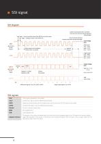
SSI diagram DATA (generated by the slave) Singleturn: 12 Bbit Multiturn: 0 Bit Coding: Gray coded output voltage level differential signals: CLK, /CLK, DATA, /DATA single ended signals: CLK, DATA
Open the catalog to page 4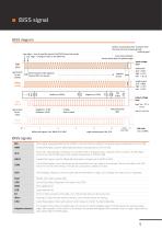
BiSS diagram neg. edge -> time to read the state of the DATA line by the master pos. edge -> change of state on the DATA line positive counting direction: clockwise from the front onto the AS bearing plate (without gear) more pulses allowed timout starts after last positive edge Ml determination of the adaptive timeout (first 1.5 pulses) Coding: binary coded input voltage level single ended (CLK - GND): high: > 2.0 V low: < 0.8 V output voltage level 8 16 differential signals: MA, NMA, SLO, NSLO single ended signals: MA, SLO 45 Bits 48 total length
Open the catalog to page 5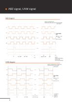
ABZ diagram positive counting direction: clockwise from the front onto the AS bearing plate (without gear) output voltage level high: (Vcc - 2.2 V) to Vcc low: 0 V to 0.4 V N: PPR (Pulses Per Revolution) 4 x PPR = CPR (Counts Per Revolution) UVW diagram positive counting direction: clockwise from the front onto the AS bearing plate (without gear) mechanical angle output voltage level high: Vcc - 2.2 V to Vcc low: 0 V to 0.4 V P: number of pole pairs 4 (number of P+1 poles
Open the catalog to page 6
Technical data subject to change! Last changes: 06/2025 Allied Motion
Open the catalog to page 8All Heidrive GmbH catalogs and technical brochures
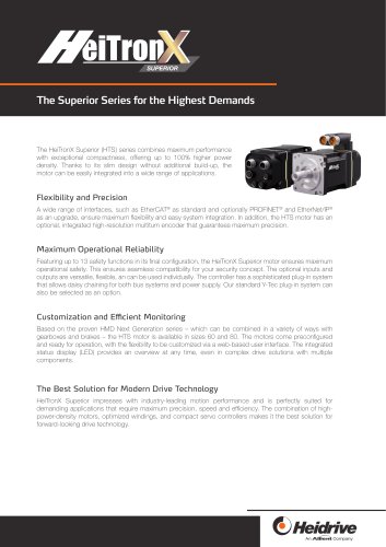 HeiTronX Superior
8 Pages
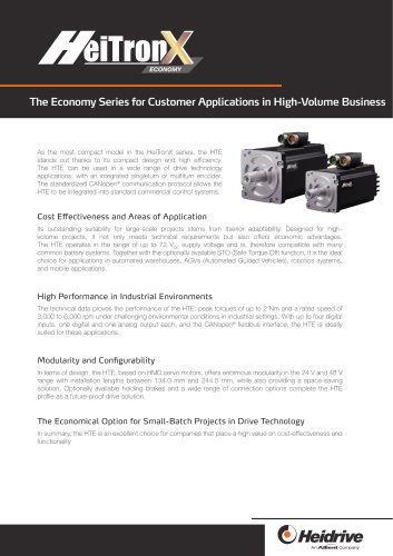 HeiTronX Economy
8 Pages
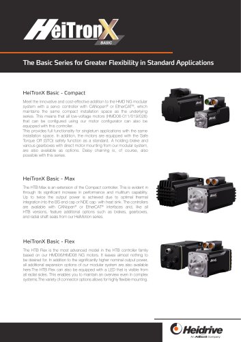 HeiTronX Basic
12 Pages
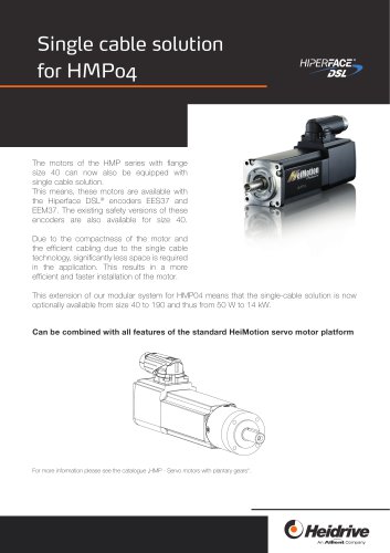 One cable solution
8 Pages
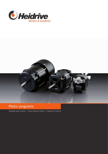 Motor programs
28 Pages
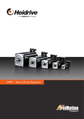 HMP - Servo drive systems
60 Pages
 Servo drives
36 Pages
 HMD Next Generation servo drives
120 Pages
 Stainless Steel Servo Motors
12 Pages
 Motion&sysystem
28 Pages
 heidrive-product
24 Pages
 EC / BLDC Motors
36 Pages
 Image brochure
8 Pages
 Flat gear type F105
12 Pages
 Gear motors compact
4 Pages


- Electromotor
- Alternating current motor
- Multipole motor
- Electric gearmotor
- Asynchronous motor
- Three-phase motor
- Direct current gear-motor
- Heidrive servomotor
- 4-pole motor
- 2-pole motor
- 380 V motor
- Servo-amplifier
- Right angle electric gearmotor
- Industrial electric gearmotor
- Coaxial gearmotor
- AC gear-motor
- Heidrive performance servomotor
- AC servo-motor
- Compact gear-motor
- 220 V motor