- Catalogs
- Hegewald & Peschke Meß- und Prüftechnik GmbH
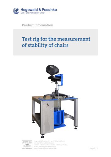
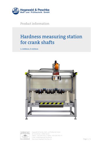
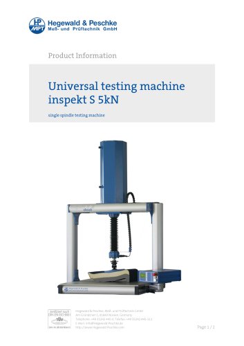
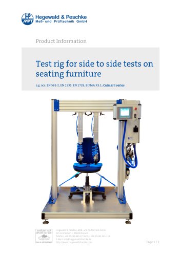
- Universal testing machine inspekt table 5 kN
- Products
- Catalogs
- News & Trends
- Exhibitions
Universal testing machine inspekt table 5 kN
1 /4Pages

Universal testing machine inspekt table 5 kN
1 /4Pages
Catalog excerpts

Product information zertifiziert nach DINEN ISO 9001 Hegewald & Peschke, MeB- und Pruftechnik GmbH Am Grundchen 1, 01683 Nossen, Germany Telephone: +49 35242 445-0, Telefax: +49 35242 445-111 E-Mail: [email protected] https://www.Hegewald-Peschke.com
Open the catalog to page 1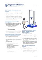
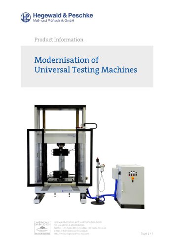
Hegewald & PeschkeMeB- und Pruftechnik GmbH Modern and flexible load frame design for various applications • Load frame extremely variable in height and width ^ optimal adaptation to different specimen and component sizes • Connection of peripheral devices (e.g. furnaces, temperature chambers) and additional measuring and control channels (e.g. extensometers, measuring probes, optical sensors) possible Innovative construction guarantees highest measuring precision • Use of backlash-free precision ball screws with larger diameter (preloaded in aluminium support profiles) and special nut system...
Open the catalog to page 2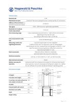
Technical data: Nominal load Mechanical structure Stiffness of the test frame (incl. deformation of load cell and tool adapter) 5 kN 2 backlash-free recirculating ball screw, covered spindle, AC-servomotor Test speed 0.001 - 2000 mm/min (optionally expandable) Resolution of crosshead <0.01 pm travel measurement Force measuring range Force measurement resolution Class 1 (optionally class 0.5) from 0.1 - 100 % of the nominal load depending on the load cell used (according to DIN EN ISO 7500-1, ASTM E4) 24 bit (±8,388,608 digits) Measuring, control and regulating electronics Data transmission Electrical...
Open the catalog to page 3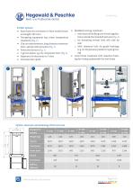
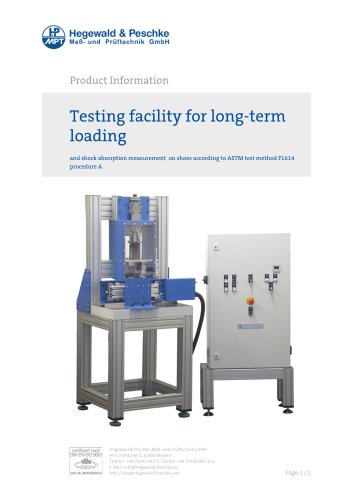
Hegewald & PeschkeMeB- und Pruftechnik GmbH Further options: • Base frame for conversion to floor model (standard height: 685 mm) • Tempering equipment (e.g. ovens, temperature chambers) [Fig. 1] • Clip-on extensometers, long-distance extensom-eters, optical extensometers [Fig. 2] • Protective devices [Fig. 3] • T-groove plates, e.g. for component tests [Fig. 4] • Expansion of electronics to 7 slots • Increased test speed • Modified moving crosshead: o with load cell shifting unit for test applications outside the standard test axis [Fig. 4] o for mounting several load cells side by side o with...
Open the catalog to page 4All Hegewald & Peschke Meß- und Prüftechnik GmbH catalogs and technical brochures
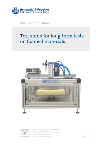
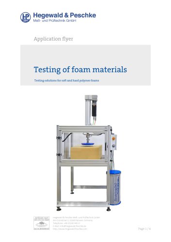 Testing of foam materials
4 Pages
 Torsion test machine
2 Pages
 Temperature chambers
4 Pages
 Length measuring machine
6 Pages
 Electromechanical test axes
4 Pages
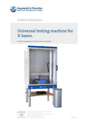
 Test rig for tables
2 Pages
 Friction test stand
2 Pages
 Stone impact tester
2 Pages
 Material testing on textiles
4 Pages
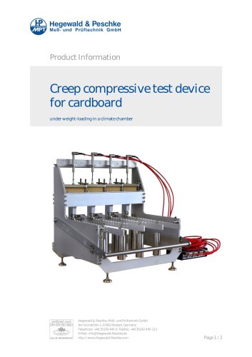
 Creep testing device
2 Pages
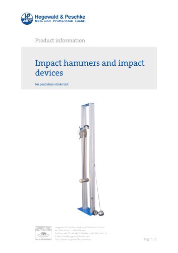
 Drop weights for drop test
3 Pages
 arm rest load pad
2 Pages
 additive weights
2 Pages
 Creep bending test device
2 Pages
 High temperature furnaces
4 Pages
 Calibration machine 2500 kN
2 Pages
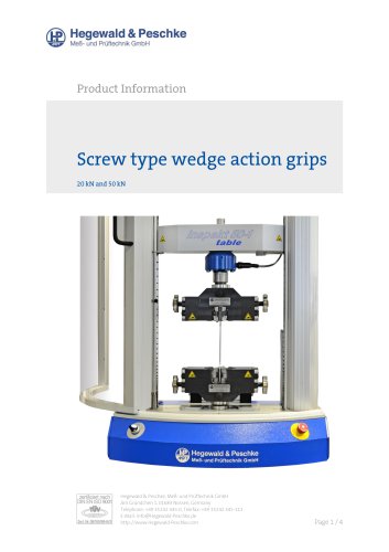
 Wedge type grips
3 Pages
 Torsion testing devices
4 Pages
 Universal linear module
2 Pages
 Ladder test stand
3 Pages
 Brinell hardness tester
2 Pages
 Magnescale Digital gauge catalog
24 Pages
 Shock test stand
2 Pages
 Load pads for arm rests
2 Pages
 Friction test stand
2 Pages


Archived catalogs
 Hydraulic grips 250kN
2 Pages
- Test machine
- Chamber kiln
- Measuring device
- Test cabinet
- Electric furnace
- Measuring machine
- Test stand
- Temperature test chamber
- Calibration system
- Material test machine
- Automated testing machine
- Indentation hardness tester
- Computer-controlled test machine
- Compression testing machine
- Benchtop hardness tester
- Laboratory kiln
- Industrial testing machine
- Vertical testing machine
- Automated test bench