SM-FT-1001 Banding Tool
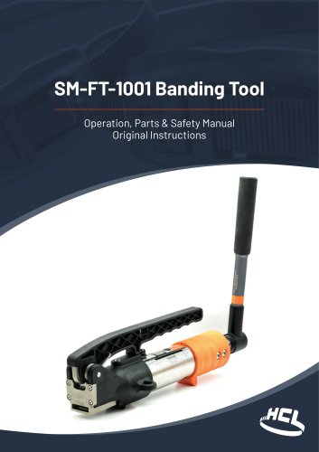
SM-FT-1001 Banding Tool
- Warning & Safety Instructions: The document stresses the necessity of proper training and the use of safety equipment such as safety glasses and gloves. It highlights potential hazards including strap breakage, eye injury, and fall risks.
- Options: Various torque wrenches are described, suitable for different Smart® Band products, with specifications on materials and marine suitability.
- Using the Tool: Step-by-step instructions are provided for using the tool with Mountz and Norbar torque wrenches, including safety warnings and torque settings.
- Servicing Instructions: Maintenance procedures are detailed, including cleaning, lubrication, and part replacement, with a recommendation for a full service after every 1000 straps or annually.
- Troubleshooting: Common issues and solutions are listed, such as incorrect torque settings and tool blockages.
- A detailed list of parts is included, with descriptions and quantities.
The document provides a detailed parts list for a banding tool used for tensioning the HCL Smart® Band systems. Components include bearings, washers, nuts, screws, and other mechanical parts, each specified with part numbers, descriptions, and quantities required.
Key Components
- Bearings and Washers: Includes thrust ball bearings, flat washers, and wave spring washers.
- Fasteners: Various nuts, capscrews, and setscrews are listed, primarily made of stainless steel.
- O-Rings and Springs: Nitrile O-rings and different types of springs (torsion, compression, handle return) are specified.
- Assemblies and Housings: Includes pawl housing overmoulded assembly and cutting blade housing.
- Blades and Pins: Cutting blades and pins of various dimensions are included.
Manufacturer Information
The manufacturer of the tool is HCL Fasteners Ltd, located in Radstock, UK. Contact details for both UK and North America offices are provided for customer support.
Product Description
The machinery described is a banding tool designed for the HCL Smart® Band 19mm and 32mm Hybrid & Compact Systems. The document emphasizes the high-quality standards of the product and provides contact information for addressing any difficulties encountered.
Additional Information
For further details and a complete range of products, customers are directed to visit the manufacturer's website.
Catalog excerpts
SM-FT-1001 Banding Tool Operation, Parts & Safety Manual Original Instructions
Open the catalog to page 1
Tooling Depending on set up, this tool is designed to assemble the following HCL Smart® products: - Smart® Band 19mm (%") Hybrid & Compact - Smart® Band 32mm (1%") Hybrid & Compact Follow the instructions described to achieve safe operation. Note: This tool is not suitable for Smart® Band Standard Systems 1.1 Warning & Safety Instructions Smart® Band Hybrid & Compact Servicing Troubleshooting Parts List COMPANY WITH QUALITY SYSTEM CERTIFIED BY DNV ISO 9001
Open the catalog to page 2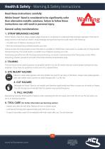
Health & Safety - Warning & Safety Instructions Read these instructions carefully: Whilst Smart® Band is considered to be significantly safer than alternative metallic solutions, failure to follow these instructions can still result in personal injury. General safety considerations: 1. STRAP BREAKAGE HAZARD Smart® Band is free from sharp metallic edges however it is important to understand that improper operation of the tool or sharp corners on the load can result in strap breakage during tensioning that could result in the following: – A sudden loss of balance causing you to fall – Both tool...
Open the catalog to page 3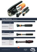
Torque Wrenches - Options Mountz – FGC-10A (Factory set to specificed torque – Suitable for Marine use). For use with: Smart® Band Hybrid 19mm (¾˝) Smart® Band Compact 19mm (¾˝) Mountz – FGC-30A (Factory set to specificed torque – Suitable for Marine use). For use with: Smart® Band Hybrid 32mm (1¼˝) Smart® Band Compact 32mm (1¼˝) Norbar – TTi20 (Variable torque setting – Not advised for Marine use). For use with: All product types PPS POM (Acetal)
Open the catalog to page 4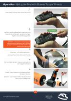
Operation - Using the Tool with Mountz Torque Wrench 1 Insert band fully into fixed end of the buckle TEETH ENGAGED Pull back band to engage latch teeth and push down firmly on the latch using the thumb or finger to ensure full engagement WARNING – Ensure latch is fully engaged with band before tightening. Latch not fully engaged could lead to premature failure of system when tightening 3 Wrap band around the application... ...and insert band into other end of buckle 4 Pull band tight by hand, making sure teeth are fully engaged with band 5 Attach Torque wrench to the square drive at the rear...
Open the catalog to page 5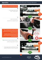
Operation - Using the Tool with Mountz Torque Wrench IMPORTANT – If Mountz type torque wrench is being utilised follow steps 6-9 followed by 18-20 6 Is the orange marker at the Start / Finish position? 7 Insert tool onto band... ...and push tool up against buckle NOTE – The Mountz torque wrench is factory set to the correct torque requirement for the specified product being used. The set torque is marked on the wrench. The torque wrench does not have a ratchet facility and will wind clockwise until the set torque is reached. At this point it will slip over with a positive click. 8 Tighten the...
Open the catalog to page 6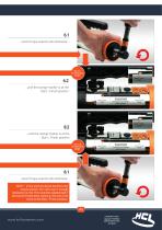
wind Torque wrench anti-clockwise Go to 7 on previous page , ...until the orange marker is at the Start / Finish position Start / Finish This does not indicate Band tension Start / Finish ...until the orange marker is at the Start / Finish position Go to 8 on previous page , Start / Finish Band tension .wind Torque wrench anti-clockwise... NOTE - In the aniti-clockwise direction, the torque wrench will click over if enough resistance is met. This could be experienced if the tool is forced when reaching the end of its travel at the Start / Finish position.
Open the catalog to page 7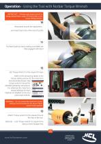
Operation - Using the Tool with Norbar Torque Wrench IMPORTANT – If Norbar type torque wrench is being utilised follow steps 10-20 and refer to the torque setting section. 10 Wrap band around the application... ...and insert band into other end of buckle 11 Pull band tight by hand, making sure teeth are fully engaged with band 12 Set Torque Wrench to the required Torque Refer to the tensioning tables in the torque setting section for the maximum recommended torque. See torque wrench manual for detailed operating instructions. For reference the maximum torque settings for each material are labelled...
Open the catalog to page 9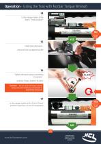
Is the orange marker at the Start / Finish position? _15 Insert tool onto band... ...and push tool up against buckle Tighten the band using a ratcheting ...until the Torque wrench 'CLICKS' WARNING - Do not wind the Torque wrench using a smooth continuous movement or beyond the click point Is the orange marker at the 'End of Travel' position? (tool has run out of movement) Start / Finish This does not indicate Band tension COMPANY WITH QUALITY SYSTEM CERTIFIED BY DNV ISO 9001
Open the catalog to page 10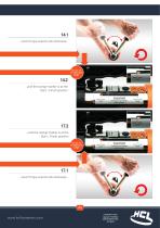
14.1...wind Torque wrench anti-clockwise...14.2 Go to 14 on previous page , ...until the orange marker is at the Start / Finish position Start / Finish This does not indicate Band tension ...until the orange marker is at the Start / Finish position Go to 16 Start / Finish This does not indicate Band tension 17.1...wind Torque wrench anti-clockwise...
Open the catalog to page 11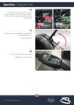
Operation - Using the Tool 18 Continue anti-clockwise rotation until the orange marker is at the ‘Start / Finish’ position. At this point the cutting clasp will release the cutting handle. 19 To remove the excess band, simply take hold of the cutting handle... ...and push upwards 20 Once cut, remove tool from buckle Installation is now complete
Open the catalog to page 12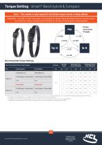
WARNING - The SM-FT-1001 tool range is not suitable for Smart® Band Standard systems. Do not exceed the maximum torque settings recommended for the Smart® Band system being applied Recommended Torque Settings Smart® Band Hybrid & Smart® Band Compact The input torque in the table above is the maximum recommended torque around a cylindrical application. This may need to be reduced depending on the following: - An irregular shaped application, e.g. an application that has sharp corners around its profile - An application in high ambient temperatures and direct sunlight, where the temperature of...
Open the catalog to page 13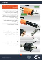
Servicing NOTE – It is advised that a full service is carried out after every 1000 straps or every year, which ever is soonest SQUARE DRIVE 1 Wind the square drive clockwise until orange marker is at the ‘End of Travel’ position Tap square drive on rear of tool to ensure rear housing is as far forward as possible (this will aid the removal of the bolts) 3 Remove M8 Buttonhead screws (4x) using 5mm hexagon key 4 Remove internal sub-assembly 5 Wind the square drive anti-clockwise to remove threaded shaft from internal housing. Thoroughly clean all parts. Apply PTFE grease to male and female threads...
Open the catalog to page 14All HCL catalogs and technical brochures
 PLAIN BAND CLAMPS
2 Pages
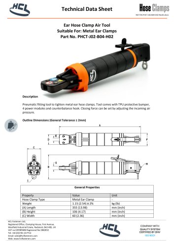 Ear Hose Clamp Air Tool
3 Pages
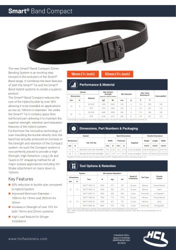 Smart Band
3 Pages