- Catalogs
- HBM Test and Measurement
- HBM eStrain Gauge Catalog
- Company
- Products
- Catalogs
- News & Trends
- Exhibitions
HBM eStrain Gauge Catalog

HBM eStrain Gauge Catalog
HBM offers a wide range of strain gauges, including series Y, C, G, V, and special gauges, adhering to OIML directive IR62 and VDI/VDE directive 2635 for precision and reliability. The document emphasizes the importance of selecting the correct connection configuration for specific applications.
The document details specifications for various strain gauge series, including resistance options (120, 350, 700, 1000 Ohm), gauge factor, temperature coefficients, and maximum permissible bridge excitation voltage. It stresses the need to match strain gauges to the thermal expansion coefficient of the test material for accurate measurements.
Different types of strain gauges are described, such as those with single, double, T rosette, and full bridges, each designed for specific applications like high strains or pressure measurement.
HBM provides accessories for strain gauge installation, including fastening materials, cleaning agents, and soldering materials. Proper installation techniques are crucial for accurate measurements.
The document discusses operating temperature range, transverse sensitivity, mechanical hysteresis, and fatigue life, highlighting the need for appropriate bonding materials and installation parameters.
For experimental stress analysis, the document explains using 3-grid rosettes for measuring biaxial stress states with unknown principal directions, providing formulas for calculating principal normal stresses.
HBM's strain gauges are designed for precision and reliability across various applications, with detailed specifications and guidelines to ensure proper selection and installation.
Strain gauges measure strain on objects and are available in resistances of 120, 350, 700, and 1000 Ohms. High resistance gauges are less sensitive to noise and have lower specific heat.
Includes linear strain gauges, T rosettes, V-shaped strain gauges, rosettes with three measuring grids, double SG, full bridge strain gauges, strain gauge chains, and diaphragm rosettes, each suited for specific measurement tasks.
Selection depends on measurement task, temperature range, and material properties. Geometry and grid length are crucial for accurate measurements, especially in inhomogeneous materials.
Strain gauges are constructed with a foil measuring grid, typically made of Constantan, and a polyimide carrier, with a nominal resistance tolerance of ±0.3% and a gauge factor of approximately 2.
Strain gauges are available in various types and configurations, with some available ex-stock. The ordering process involves specifying type and temperature response matching.
Includes material properties, temperature coefficients, mechanical hysteresis, maximum elongation, and fatigue life, critical for ensuring accurate and reliable measurements.
The document provides detailed specifications and descriptions of various strain gauges and accessories in Series Y, designed for different materials and applications.
Includes models like RY101 and RY103, with temperature response matched to materials like steel and aluminum.
Includes models like VY11 and VY41, with temperature response matched to steel and aluminum.
Includes models like KY11 and KY21, with temperature response matched to steel.
Includes prewired PVC ribbon cable, available in various lengths, with temperature response tailored to different materials.
Nominal resistance options, operating temperature range, mechanical hysteresis, and fatigue life details are provided for specific SG types.
The document provides detailed specifications and options for various types of strain gauges and accessories, focusing on their temperature response, dimensions, and application suitability.
Includes temperature response, dimensions, resistance, and installation procedures.
Includes installation guidelines, temperature range suitability, and adhesive recommendations.
Includes material specifications and mechanical properties.
Includes variants and availability, dimensions, and voltage data.
The document serves as a comprehensive guide for selecting and applying strain gauges in various industrial applications.
The document provides detailed specifications and guidelines for various series of HBM strain gauges, including their construction, materials, temperature responses, and application recommendations.
Includes details for Series C, G, V, and LE11, with temperature responses and mechanical properties.
Details the temperature response of strain gauges matched to materials like steel and aluminum.
Includes information on mechanical hysteresis, maximum elongation, and fatigue life.
Suggests suitable bonding materials and provides installation guidelines.
Includes dimensions, resistance values, and other critical parameters.
The document provides detailed specifications and applications for various types of strain gauges and accessories.
Lists strain gauge models with specific nominal resistance, dimensions, and maximum permissible excitation voltage.
Highlights the use of strain gauges in various fields and bonding methods like spot welding.
Specifies operating temperature ranges and material compatibility.
Describes models with rapid response times and pressure measurement capabilities.
Recommends bonding methods based on application and environmental conditions.
Used to monitor crack growth, with connection diagrams provided.
Describes methods for determining residual stresses using strain gauge rosettes.
The document provides detailed technical specifications and procedures for using strain gauges in residual stress analysis.
Includes details for strain gauges like XY51 and RY51 rosettes.
Outlines the ring core and hole-drilling methods for residual stress analysis.
Includes various types of strain gauges for different applications.
Details the use of adhesives for bonding strain gauges.
Recommends selecting adhesives based on application temperature and material compatibility.
Mentions availability of customized strain gauges and the MTS3000 system for automated residual stress determination.
Details various epoxy resin adhesives and strain gauge accessories.
Outlines proper installation and multi-layer covering procedures.
Includes protection against humidity and mechanical damage.
Includes chemical resistance and temperature ranges for covering materials.
Highlights incompatible covering agents and specifies soldering terminals and cables.
Provides detailed specifications for cables and strain gauges.
Outlines the use of strain gauges and accessories, including installation kits.
Includes recommendations for solder and bridge completion resistors.
Describes various amplifier systems for measurement tasks.
Highlights software solutions for data acquisition and analysis.
Introduces optical strain gauges for environments with electromagnetic interference.
HBM offers seminars for practical training in electrical measurement.
A specialized book is available for practical insights into measurement using strain gauges.
Catalog excerpts

HBM strain gauges © Hottinger Baldwin Messtechnik GmbH. All rights reserved. All details describe our products in general form only. They are not to be understood as express warranty and do not constitute and liability whatsoever. Strain Gauges Absolute precision from HBM HBM Test and Measurement
Open the catalog to page 1
Strain gauges Absolute precision from HBM
Open the catalog to page 3
From measured strain to mechanical stress... 12 The easy way to find the right strain gauge 14 with 1 measuring grid / linear SG 20 with 2 measuring grids / double SG 24 with 2 measuring grids / T rosette 25 with 2 measuring grids / Shear/torsion SG / T rosette 27 with 2 measuring grids / Torsion/shear SG 28 with 3 measuring grids / rosettes 29 with 4 measuring grids / full bridges 33 with 4 measuring grids / diaphragm rosettes 34 SG with connection cable K-LY.../K-XY.../K-RY.../K-DY... 39 (incl. Teflon wire) with 1 measuring grid 41 (incl. Teflon wire) with 2 measuring grids 42 (incl. Teflon...
Open the catalog to page 4
Encapsulated SG with 3m (10 ft) stranded connection wire 54 Encapsulated SG with stranded wire 55 Strain gauges for integration in composites 58 Pressure measurement gauge 60 Crack propagation gauges 61 SG for determination of residual stress 63 Integral hole drilling method 68 Customized strain gauges 69 Cleaning agents, gluing and soldering materials 75 Cables and stranded wires 77 Bridge completions/resin-cored solder/lead-free solder 80 Optical strain gauges 86 HBM Strain gauges and accessories
Open the catalog to page 5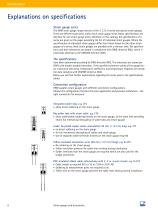
Explanations on specifications Strain gauge series The HBM strain gauge range consists of the Y, C, G, V series and special strain gauges. There are different type series within each strain gauge series. Many specifications are identical for one strain gauge series; therefore, in this catalog, the specifications of a series are given on the pages preceding the list of individual strain gauges. Where the specifications of individual strain gauges differ from those stated for the other strain gauges of a series, these strain gauges are provided with a relevant note. The specifications and their...
Open the catalog to page 6
Strain gauge dimensions The specified active measuring grid length “a” is the net length of the grid without the end loops (transverse bridges). If the following facts are taken into account, it is possible to cut the carrier foil: Cutting the foil in parallel to the measuring grid has only minor effects. Shortening the carrier foil perpendicular to the measuring grid influences the way the strain is introduced, thereby also changing essential characteristics of the strain gauge. A minimum distance of 1mm (0.04 inch) between the measuring grid end and the end of the carrier foil should therefore...
Open the catalog to page 7
Maximum permissible effective bridge excitation voltage A strain gauge is a resistor, converting electrical energy into heat. To prevent heating of the strain gauge it is essential to choose a supply voltage that is not excessively high. The maximum permissible bridge excitation voltage is calculated for each strain gauge and is listed in a table in this catalog. The specified excitation voltage always applies for the Wheatstone bridge as a whole. Only half the voltage may be applied to the individual strain gauge. The maximum values specified are permissible only for application on materials...
Open the catalog to page 8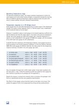
Operating temperature range The operating temperature range is the range of ambient temperatures in which the strain gauge can be used without lasting changes in measurement properties occurring. There are different operating temperature ranges for absolute (with zero point reference) or relative (without zero point reference) measurements. Temperature response in a 1/4-bridge circuit Strain gauges that are connected individually show an output signal, if the temperature changes. This signal is called “apparent strain” or “thermal output” and is independent of the mechanical load on the test...
Open the catalog to page 9
The temperature response involves a tolerance and only applies in the temperature range of the temperature response matching. This temperature range is specified in the specifications of the individual series in this catalog. Another possibility of compensating the apparent strain is to use appropriate wiring (e.g. circuit with compensating strain gauge, half bridge circuit, etc.). Mechanical hysteresis The mechanical hysteresis of a strain gauge is defined as the difference of the measured value displayed for increasing and decreasing strain loadings with the same strain value on the specimen....
Open the catalog to page 10
Minimum radius of curvature The flexibility of a strain gauge is characterized by the minimum radius of curvature which it will withstand, without any auxiliary measures, in each direction respectively. The polyimide carriers of Y and C series strain gauges are flexible to an extent that they can be bonded around edges. Although the carrier materials of the other strain gauge series are more brittle, they can also be easily prepared for application to smaller radii by thermal pre-forming Exception: V series strain gauges have a bigger radius of curvature because of their specific potting. Fatigue...
Open the catalog to page 11
From measured strain to mechanical stress ... Analysis of the biaxial stress state with unknown principal directions The principle of experimental stress analysis using strain gauges (SG) consists in using strain gauges to measure strains on the component surface. From these measured strains and the known material properties (modulus of elasticity and Poisson’s ratio), the absolute value and the direction of these mechanical stresses are determined. These calculations are based on Hooke’s Law which applies to the elastic deformation range of linear-elastic materials. In experimental stress analysis,...
Open the catalog to page 12
The principal directions are determined below. First the tangent of an auxiliary angle \\i For the 0°/45°/90° rosette using the formula: and for the 0°/60°/120° rosette according to the formula: Note: The tangent of an angle in the right-angled triangle is the ratio of the opposite side (numerator N) to the adjacent side (denominator D): This ambiguity of the tangent makes it necessary to determine the signs of the numera- tor (N) and the denominator (D) before carrying out the final calculation of the two above mentioned quotients. Determining the signs is important because they alone indicate...
Open the catalog to page 13All HBM Test and Measurement catalogs and technical brochures


Archived catalogs
 PMX Measuring amplifier system
16 Pages
 PACEline
10 Pages
 QuantumX
14 Pages
 Pressure
8 Pages
 Torque T40B
8 Pages
 Digital Weighing Brochure
8 Pages
 Strain Gages and Accessories
100 Pages


- Connector
- Data connector
- HBM load cell
- Analysis software solution
- Pressure transmitter
- Tension/compression force transducer
- Process software
- Windows software
- Real-time software
- HBM steel load cell
- Calibration system
- Analog pressure transmitter
- Strain gauge force sensor
- Acceleration sensor
- HBM stainless steel load cell
- Pressure probe
- Weighing force transducer
- Monitoring software solution
- Industrial software
- Membrane pressure transmitter