

Oil coolers
Oil coolers
The document outlines various oil cooler models for industrial and mobile applications. Key materials include aluminum for cooler blocks, steel for fan housings, and plastic/aluminum for axial fans. The coolers are powder-coated for enhanced durability.
Oil coolers can operate at a maximum pressure of 16 bar and temperatures up to 120°C. They are compatible with various hydraulic fluids, feature low noise levels, and are easy to maintain. Electric motors range from 230-400V, with different efficiency classes.
Cooling capacity is tested with ISO VG 46 oil at a 60°C inlet temperature. Actual performance may vary by ±5% depending on installation and operating conditions.
Each cooler type is specified with motor power, power consumption, rotation speed, air flow, noise level, and weight. For instance, the ACI-11-400-4 model has a motor power of 0.18 kW and a noise level of 51 dB(A).
Installation should minimize stress on the heat exchanger, using flexible hoses or compensators to prevent fatigue failure from pressure peaks.
Oil coolers extend oil life, improve seal and component longevity, and offer flexibility in pump selection. They are suitable for various hydraulic applications, including mobile units in agriculture and construction.
Ordering codes specify cooler series, size, voltage, mounting position, air flow direction, and additional options like internal bypass valves.
Pressure drop calculations are provided for different viscosities, with conversion factors for various ISO VG grades.
Different series like ACI, ACIP, and ACM cater to specific industrial and mobile needs, with features like integrated motor-pump units and DC drives for mobile applications.
Catalog excerpts
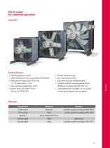
Product features • Static test pressure 25 bar according to DIN 50104 • Peak pressure resistance at 16 bar and 1 x 10⁶ load cycles, f = 1Hz Powder-coated housing Low sound pressure level Easy cleaning of the cooling elements Operation with all common hydraulic fluids Cooling block also available in 2-way design or with internal bypass-valve on request
Open the catalog to page 3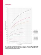
Specific cooling capacity Pspez [W/K] Cooling capacity Flow rate Q [l/min] The specific cooling capacity indicated in the graph was determined on the test bench, test oil ISO VG 46, oil-inlet temperature 60°C. The actual cooling capacity may deviate by approx. ± 5 % depending on the installation site and other operating parameters.
Open the catalog to page 4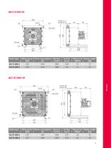
Cooler type Cooler type
Open the catalog to page 5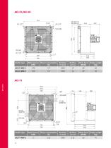
Cooler type
Open the catalog to page 6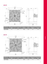
Cooler type Cooler type
Open the catalog to page 7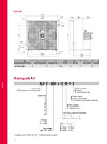
Cooler type ACI = cooler for industrial application Input voltage * possible with AG-7'/-8'/-9'/-'0' ** additional options on request Additional options** Mounting options 0 = standard: feet mounted 1 = horizontally mounted with special bracket Mounting position of cooler block Engine revolution
Open the catalog to page 8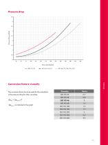
The correction factor has to be used for the calculation of the pressure drop for other viscosities:
Open the catalog to page 9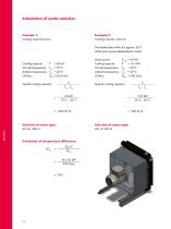
Calculation of cooler selection Example 2: Cooling capacity unknown Example 1: Cooling capacity known The heattransfer to the oil is approx. 30 % of the motor power (diesel/electric motor) Cooling capacity Oil inlet temperature Ambient temperature Oil flow P = 65 kW TOil = 70°C TAir = 20°C QOil = 300 l/min P TOil - TAir Specific cooling capacity: Selection of cooler type: ACI-61-400-4 PMotor = 45 kW P = 13.5 kW TOil = 50°C TAir = 20°C QOil = 200 l/min P TOil - TAir Specific cooling capacity: Selection of cooler type: ACI-31-400-4 Calculation of temperature difference: ΔTOil Motor power Cooling...
Open the catalog to page 10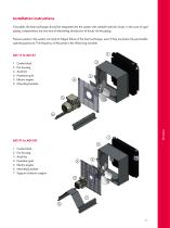
Installation instructions If possible, the heat exchanger should be integrated into the system with suitable hydraulic hoses. In the case of rigid piping, compensators are one way of eliminating introduction of forces via the piping. Pressure peaks in the system can lead to fatigue failure of the heat exchanger, even if they are below the permissible operating pressure. The frequency of the peaks is the influencing variable. 7 Support of electric engine
Open the catalog to page 11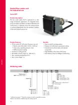
Partial flow cooler unit for industrial use Series ACIP The new cooler system ACIP is optimised for a wide range of hydraulic applications. An integrated motor pump unit makes it possible to cool the oil efficiently and continuously in a separate circuit. The cooling process is working independently from the operation condition of the main hydraulic power unit. • Oil-air cooler ACI with motor & pump in one unit • Gear pump, operating pressure: 4 bar • Continuous cooling process • Permissible viscosity range: 10 - 300 mm2/s • Easy to retrofit in existing systems • Extension of oil life due to...
Open the catalog to page 12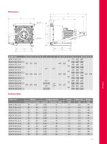
Cooler size Technical data Cooler size
Open the catalog to page 13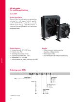
Oil-air cooler Series ACM Product description The new ACM oil-air cooler series is an optimised heat exchanger for a wide range of hydraulic applications. The 12/24V DC drive enables the use in mobile hydraulic power units, e.g. in agriculture/ forestry, in construction and mining machinery and in the loading and transport sector. Product features • Compact fans with 12/24V DC drive • Cooling capacity: 3 - 50kW (referring to AT=40K) • Different sizes and cooling capacities depending on the application • Internal bypass valve • Short delivery times by intelligent warehousing Input voltage motor...
Open the catalog to page 14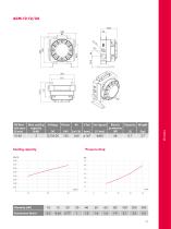
Pressure drop Cooling capacity Viscosity [cSt]
Open the catalog to page 15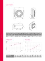
Pressure drop Cooling capacity Viscosity [cSt]
Open the catalog to page 16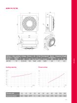
Pressure drop Cooling capacity Viscosity [cSt]
Open the catalog to page 17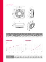
Pressure drop Cooling capacity Viscosity [cSt]
Open the catalog to page 18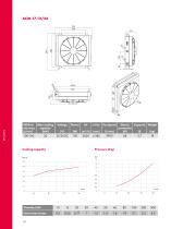
Pressure drop Cooling capacity Viscosity [cSt]
Open the catalog to page 20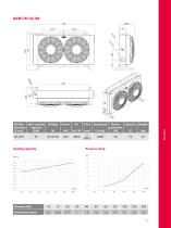
Pressure drop Cooling capacity
Open the catalog to page 21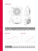
Cooling capacity Pressure drop Viscosity [cSt]
Open the catalog to page 22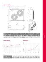
Pressure drop
Open the catalog to page 23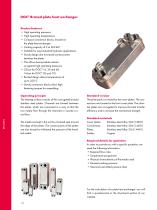
Product features • High operating pressures • High operating temperatures • Compact connection blocks, brazed on the plate heat exchanger • Suitable for most industrial hydraulic applications • Sturdy design due to brazed contact points between the plates • This allows best possible resistance against high operating pressures • Brazed design allows temperatures of up to 225°C • Sturdy connection blocks allow high fastening torques for assembling Operating principle The heating surface consists of thin corrugated brazed stainless steel plates. Channels are formed between the plates; which are...
Open the catalog to page 24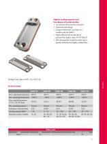
Highest cooling capacity and • Low pressure drop over the connectors • Optimised plate design • Compact dimensions, low water consumption and low Delta T • Highly efficient heat transfer due to turbulent flow (high k value; P=k*A*Delta T) • Self cleaning effect inside the cooler due to equally distributed and highly turbulent flow Technical data
Open the catalog to page 25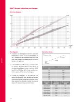
DOC® Brazed plate heat exchanger Selection diagram kW HP The diagram • is based on an oil temperature of 60°C and water temperature of 20°C. For an oil temperature of 50°C, multiply with the correction factor of 0.7. For other water temperatures, please see the correction factors on the right side. • is calculated for two different oil / water flow rates: 2:1 and 4:1. This means that for every litre of oil circulated through the oil cooler, a minimum of 0.5 litres (2:1) or 0.25 litres (4:1) of water must be circulated to agree with the data in the diagram. • is based on oil (ISO VG 32). For other...
Open the catalog to page 26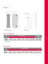
DOC® Dimensioning Support bracket Plate heat exchanger DOC® Type Dimensions [mm] Dry weight
Open the catalog to page 27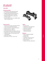
• Development of a tube bundle heat exchanger • For a wide range of industrial applications • Additional cooling surface due to aluminium fins for a heat exchange capacity of 1,000 kW • EKM heat exchangers have a cooling surface of 0.43 m2 to 56 m2 • Are constructed of 43 basic units, available as single, double or quadruple version Product features • Aluminium fins and copper nickel tubes (standard) ensure maximum level of heat exchange • Large oil connectors for minimum flow resistance • Oil flow rates of up to 1,200 l/min • Removable end caps for easy cleaning of the tubes • Flanges allow...
Open the catalog to page 29All HBE GmbH catalogs and technical brochures
 HBE product catalogue
188 Pages
 air oil cooler ACI
12 Pages
 partial flow cooler ACIP
4 Pages
 Oil tanks welded steel
14 Pages
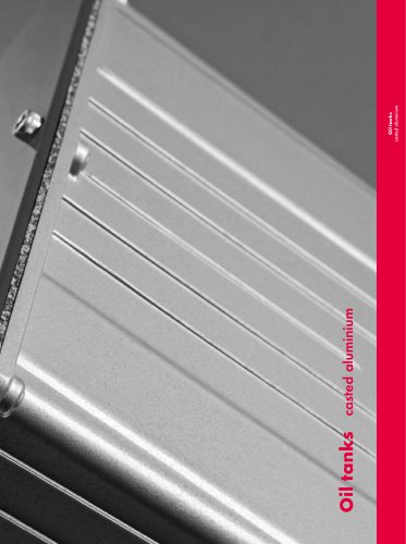 Oil tanks casted aluminium
14 Pages
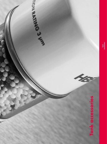 Tank accessories
16 Pages
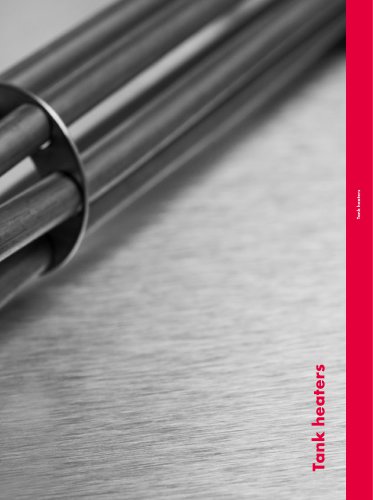 Tank heaters
20 Pages
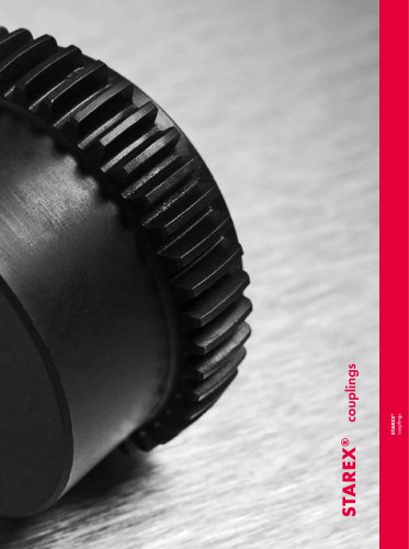 STAREX® couplings
8 Pages
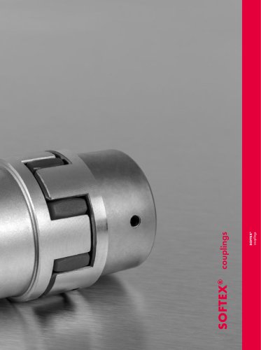 SOFTEX® couplings
20 Pages
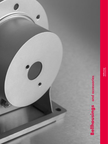 Bellhousings and accessories
32 Pages
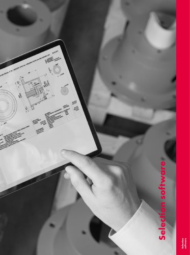 Selection software
4 Pages

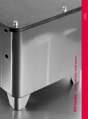

- Vessel
- Storage vessel
- Level limit switch
- Liquid level detector
- Filter with cartridge
- Metal tank
- Liquid recirculation chiller
- Stainless steel vessel
- HBE flexible coupling
- Shaft shaft coupling
- Stainless steel pre-filter
- Industrial tank container
- Float level switch
- Liquid/liquid heat exchanger
- Water recirculation chiller
- Resistance heater
- Flange coupling