
- Catalogs
- Hayward Industries, Inc.
- Needle Valves

Needle Valves

Needle Valves
This document provides installation data for Hayward needle valves, emphasizing the importance of following the instructions to prevent injury and ensure proper operation.
Product Guarantee and Responsibility
Hayward guarantees its products against defects in material and workmanship but does not assume responsibility for damages or injuries due to improper installation, misapplication, or chemical incompatibility. Users should verify compatibility and suitability for their specific applications.
Operating Conditions
Users must consult Hayward literature to understand the operating pressure and temperature limitations. The maximum recommended fluid velocity is eight feet per second to avoid damage from the water hammer effect. Hayward products are designed for non-compressible liquids and should not be used with compressible fluids.
Installation and Maintenance
Systems should be depressurized and drained before installation or maintenance. Consider temperature effects on piping systems to prevent mechanical loading on Hayward equipment. Caution is advised when using PVC and CPVC products below 40°F due to brittleness.
Torque and Material Considerations
Valve torque requirements are based on tests with clean water at 70°F. Factors such as fluid chemistry and temperature should be considered when sizing actuators. Direct installation of metal pipes into plastic connections is not recommended due to differential thermal expansion rates.
Threaded Connection Instructions
Threaded connections should follow ASTM and ANSI specifications. Teflon tape should be applied to pipe threads to ensure a leak-proof joint, with specific instructions on wrapping and tightening.
Installation Considerations for Needle Valves
Needle valves are designed to regulate flow and shut off completely. The flow direction is critical and indicated by an arrow on the valve body. Flow adjustment is achieved by rotating the handwheel.
Component Description
The needle valve consists of several components: body, handwheel, bonnet, O-ring seal, stem, and Teflon seat.
Non-Shock Operating Pressures
The document references non-shock operating pressures, although specific values are not provided.
Catalog excerpts
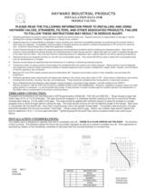
1. Hayward guarantees its products against defective material and workmanship only. Hayward assumes no responsibility for damage or injuries resulting from improper installation, misapplication, or abuse of any product. 2. Hayward assumes no responsibility for damage or injury resulting from chemical incompatibility between its products and the process fluids to which they are subjected. Compatibility charts provided in Hayward literature are based on ambient temperatures of 70F and are for reference only. Customer should always test to determine application suitability. 3. Consult Hayward literature to determine operating pressure and temperature limitations before installing any Hayward product. Note that the maximum recommended fluid velocity through any Hayward product is eight feet per second. Higher flow rates can result in possible damage due to the water hammer effect. Also note that maximum operating pressure is dependent upon material selection as well as operating temperature. 4. Hayward products are designed primarily for use with non-compressible liquids. They should NEVER be used or tested with compressible fluids such as compressed air or nitrogen. 5. Systems should always be depressurized and drained prior to installing or maintaining Hayward products. 6. Temperature effect on piping systems should always be considered when the systems are initially designed. Piping systems must be designed and supported to prevent excess mechanical loading on Hayward equipment due to system misalignment, weight, shock, vibration, and the effects of thermal expansion and contraction. 7. Because PVC and CPVC plastic products become brittle below 40F, Hayward recommends caution in their installation and use below this temperature. 8. Published operating torque requirements are based upon testing of new valves using clean water at 70F. Valve torque is affected by many factors including fluid chemistry, viscosity, flow rate, and temperature. These should be considered when sizing electric or pneumatic actuators. 9. Due to differential thermal expansion rates between metal and plastic, transmittal of pipe vibration, and pipe loading forces DIRECT INSTALLATION OF METAL PIPE INTO PLASTIC CONNECTIONS IS NOT RECOMMENDED. Wherever installation of plastic valves into metal piping systems is necessary, it is recommended that at least 10 pipe diameter in length of plastic pipe be installed upstream and downstream of the plastic valve to compensate for the factors mentioned above. > NVIS REV C 9/3/99 ECR 819R DETAIL DESCRIPTION 1 BODY 2 HANDWHEEL 3 BONNET NON SHOCK OPERATING PRESSURES 4 ԓO-RING SEAL 5 STEM 6 TEFLON SEAT >
Open the catalog to page 1All Hayward Industries, Inc. catalogs and technical brochures
 NPP0412A - TB Series in GFPP
2 Pages
 Industrial Product Guide
164 Pages
 Hayward Condensed Product Guide
36 Pages
 Chemical Resistance Guide
13 Pages
 WPP-19 Corrosion-Resistant Pumps
20 Pages
 ACT-06 Actuation and Controls
32 Pages
 Solenoid Valves - IOM
4 Pages
 Pneumatic Actuator Model PCD/PCS
10 Pages
 Electric Actuator Model EJM
6 Pages
 Bag Filter - PVDF
2 Pages
 Bag Filter - PPL
2 Pages
 Duplex Basket Strainers
4 Pages
 Cartridge Filter
2 Pages
 Simplex Basket Strainers
2 Pages
 Duplex Bag Filter
2 Pages
 Y Strainers
2 Pages
 QIC Valves
2 Pages
 Y Check Valves
2 Pages
 Pressure Regulators
2 Pages
 Vacuum Breaker
2 Pages
 Universal Stopcock
2 Pages
 Three Way True Union Valves
2 Pages
 Gauge Guards
2 Pages
 True Union Ball Check Valves
2 Pages
 Foot Valve Screens
1 Page
 Diaphragm Valves 3" to 6"
2 Pages
 Diaphragm Valves 1/2" to 2"
2 Pages
 Bulkhead Fittings
2 Pages
 Swing Check Valves
2 Pages
 Butterfly Valves 14" to 24"
2 Pages
 Relief Valves
2 Pages
 Angle Valves
2 Pages


