Catalog excerpts
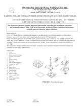
ONE HAYWARD INDUSTRIAL DRIVE CLEMMONS, NC 27012 PHONE (336)-712-9900 FAX (336) 712-9518 PARTS LIST > 1 Cover 2 Cover Screws 3 Gasket (shown) or O-ring (weather proof models) 4 Base 5. > Output coupling 6. > Bull Gear 7. > Bull Gear Retaining Ring 8. > Output/Cam Shaft 9. > Cams 10. > Mother Board 11. > Mother Board Bracket 12. > Limit Switches 13. > Override Shaft 14. > Motor Gear Box 15. > Motor Support Plate screws 16. > Motor Support Plate 17. > Pinion Gear
Open the catalog to page 1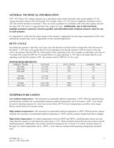
EVS - EVT Series AC voltage actuators use a split phase motor which internally steps up the applied 115 AC voltage and feeds it back to the off terminal. For example, when 115 VAC power is applied at terminals I and 4, 230 volts will be fed back to terminal 3. This can create a problem for controllers with solid state outputs rated for less than 230 VAC and it is suggested that relay outputs be used. > It is important to verify that the output torque of the actuator is appropriate for the torque requirements of the valve and that the actuator duty cycle is appropriate for the intended...
Open the catalog to page 2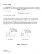
: 1/16 inch hex wrench small flat blade screw driver 1/2 inch open or box wrench - large enclosures 3/16 inch hex wrench - small enclosures > The actuator may be mounted in any position. In outdoor applications the actuator should not be installed upside down. Verify that the output torque of the actuator is appropriate for the torque requirements of the valve. All actuators are furnished with a female drive output. On the EVT Series actuators, the output is 0.75" square by 0.75" deep. On the EVS Series actuators, the output is 1.00" square by 1.40 deep. Two ISO. bolt patterns (ISO 5211)are...
Open the catalog to page 3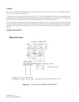
EVSIOM Rev A June 23, 1999 ECR 819R 4 WIRING > For 115 VAC actuators, 18 or 20 gauge wire may be used for short runs. At least 16 gauge wire is recommended for longer runs. Be sure to follow local wiring codes. To operate an electric actuator, power (which may be 24, 115, or 230 VAC dependent on the actuator - please match before wiring as the wrong voltage will destroy the motherboard) from the user is wired directly to the actuator's motor through two limit switches. The limit switches control the actuators mechanical travel limits, usually 90 degrees. To drive the actuator...
Open the catalog to page 4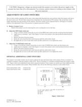
The two limit switches operating off the cams on the output shaft determine the exact positions where the actuator will stop at the end of each cycle. The first limit switch (lower) determines the closed position (CW rotation). The second limit switch (upper) determines the open position (CCW rotation). The limit switches can be adjusted from5 to 320 degrees of actuator rotation. If an adjustment of any of the positions is required, proceed as follows: A. Remove Actuator Cover Remove the actuator cover by removing the screws securing the cover to the base. B. Adjust the OPEN limit switch...
Open the catalog to page 6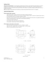
Manual Override Function: To use the manual override function, push the override shaft down approximately a1/4 inch to disengage the motor from the gear train. While holding the shaft down, turn the shaft with a wrench to reach the desired position. Be careful not to drive the actuator past the limit switch settings; it is possible to damage installed options such as a feedback potentiometer. Note: The manual override shaft must be returned to its fully upward position before the motor is re-engaged. > Check that the proper voltages are present at the actuator's terminal connections. Check...
Open the catalog to page 7All Hayward Industries catalogs and technical brochures
-
NPP0412A - TB Series in GFPP
2 Pages
-
Industrial Product Guide
164 Pages
-
Hayward Condensed Product Guide
36 Pages
-
Chemical Resistance Guide
13 Pages
-
WPP-19 Corrosion-Resistant Pumps
20 Pages
-
ACT-06 Actuation and Controls
32 Pages
-
Solenoid Valves - IOM
4 Pages
-
Pneumatic Actuator Model PCD/PCS
10 Pages
-
Electric Actuator Model EJM
6 Pages
-
Differential Pressure Switch
1 Pages
-
Bag Filter - PVDF
2 Pages
-
Differential Pressure Gauge
1 Pages
-
Bag Filter - PPL
2 Pages
-
Duplex Basket Strainers
4 Pages
-
Cartridge Filter
2 Pages
-
Simplex Basket Strainers
2 Pages
-
Duplex Bag Filter
2 Pages
-
Y Strainers
2 Pages
-
QIC Valves
2 Pages
-
Y Check Valves
2 Pages
-
Pressure Regulators
2 Pages
-
Vacuum Breaker
2 Pages
-
Needle Valves
1 Pages
-
Universal Stopcock
2 Pages
-
Three Way True Union Valves
2 Pages
-
Gauge Guards
2 Pages
-
True Union Ball Check Valves
2 Pages
-
Foot Valve Screens
1 Pages
-
Diaphragm Valves 3" to 6"
2 Pages
-
Diaphragm Valves 1/2" to 2"
2 Pages
-
Bulkhead Fittings
2 Pages
-
Swing Check Valves
2 Pages
-
Butterfly Valves 14" to 24"
2 Pages
-
Relief Valves
2 Pages
-
Angle Valves
2 Pages


