- Catalogs
- Hayward Industries, Inc.
- Electric Actuator Model EJM
Electric Actuator Model EJM

Electric Actuator Model EJM
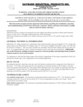
This document is an instruction manual for the Hayward Controls EJM Series Electric Actuators, detailing installation, operation, and troubleshooting procedures. It emphasizes the importance of following instructions to prevent serious injury or death.
Description
The EJM Series Electric Actuators are designed for reliable operation of control elements like 1/4 turn valves, with torque requirements up to 3500 inch pounds. They are available in AC models with 25% or 75% duty cycles and DC models with a 100% duty cycle.
General Technical Information
The actuators use a split phase motor that steps up the applied voltage, which can affect controllers with solid state outputs. It is recommended to use "clean" contacts for feedback and ensure individual wiring for each actuator.
Duty Cycle
Exceeding the rated duty cycle can cause the thermal overload switch to shut off power. A 25% duty cycle requires the actuator to be off for three times the operating cycle, while a 75% duty cycle requires it to be off for one-third of the cycle.
Temperature Limits
The recommended ambient temperature range is -23°F to 140°F. Lower temperatures can affect valve torque, and high temperatures require shading from direct sunlight.
Power Requirements
The document provides detailed current requirements for various models under different voltage conditions, highlighting the torque and speed specifications.
Installation
Actuators can be mounted in any position but should not be installed upside down outdoors. They must be securely mounted to prevent backlash and side-loading.
Wiring
Specific wiring instructions are provided for different voltage actuators, emphasizing the importance of matching voltage to prevent damage.
Modulating Control Board Setup
Instructions for DIP switch settings are provided for different input and output signals, as well as settings for loss of signal and deadband adjustments.
Adjustment of Limit Switches
Detailed steps are provided for adjusting the limit switches that control the actuator's open and closed positions.
Troubleshooting Guide
The guide lists common issues, possible causes, and remedies, such as checking power sources, replacing motors, and adjusting limit switches.
Limited Warranty
Hayward offers a two-year limited warranty against defects in material and workmanship, with specific exclusions and conditions outlined.
Catalog excerpts
ONE HAYWARD INDUSTRIAL DRIVE CLEMMONS, NC 27012 PHONE (336)-712-9900 FAX (336) 712-9518 DESCRIPTION EJM Series Electric Actuators are designed to provide reliable and efficient operation of final control elements, such as 1/4 turn valves, with torque requirements up to 3500 inch pounds. EJM Series actuators are available as AC models with duty cycles of 25% or 75% and DC models with a 100% duty cycle. > EJM Series AC voltage actuators use a split phase motor which internally steps up the applied 115 AC voltage and feeds it back to the off terminal. For example, when 115 VAC power is applied at terminals 1 and 4, 230 volts will be fed back to terminal 3. This can create a problem for controllers with solid state outputs rated for less than 230 VAC. It is suggested that the cleanӔ contacts provided be used for solid state device feed back. > It is important to verify that the output torque of the actuator is appropriate for the torque requirements of the valve and that the actuator duty cycle is appropriate for the intended application. > Exceeding the actuator's rated duty cycle may cause the thermal overload switch to temporarily shut off power to the motor. A 25% duty cycle means that for every operating cycle that the actuator is ON (to open or close the valve), the actuator must be OFF for a time equal to three operating cycles. For example, an operating cycle time of 5 seconds ON, it must be OFF for 15 seconds before it is again operated. A 75% duty cycle means that for every operating cycle that the actuator is ON, the actuator must be OFF for 1/3 of a cycle. > Low ambient temperatures : The minimum recommended ambient temperature is -23 F. Care should be used in selecting actuators for valves for services below 40 а F as lower temperatures can affect valve torque. Please consult factory for actuator sizing. High ambient temperatures : The maximum recommended ambient temperature is 140 F with the actuator shaded from direct sunlight. > EJMIOM.DOC REV B May 5, 2005 ECR 930T size="-1">
Open the catalog to page 1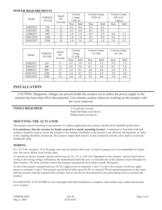
: 1/16 inch hex wrench Small flat blade screwdriver Philips head screwdriver > The actuator may be mounted in any position. In outdoor applications the actuator should not be installed upside down. It is mandatory that the actuator be firmly secured to a sturdy mounting bracket . A minimum of four bolts with lock washers; should be used to secure the actuator to the bracket. Flexibility in the bracket is not allowed, and backlash, or "play", in the coupling should be minimized. The actuator output shaft must be in line (centered) with the valve shaft to avoid side- loading the shaft. > For 115...
Open the catalog to page 2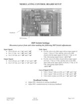
Input Signal: For 4-20 mA, set 1 Փ on and 2 ԓ off ԕ For the valve to be fully open with an input signal of 4 mA, 1 Vdc or 2 Vdc; and the valve to be fully closed with the input signal of 20 mA, 5 Vdc, or 10 Vdc, (Increasing signal closes) ֕ For 1-5 Vdc, set 1 off Ӕ and 2 off Ӕ set 6 onӔ For 2-10 Vdc, set 1 Փ off and 2 ԓ on Ouput Signal: Loss of Signal (LOS) ԕ For the valve to be fully closed with an input signal of 4 mA, 1 Vdc or 2 Vdc; and the valve to be fully open with an the input signal of 20 mA, 5 Vdc, or 10 Vdc, (Increasing signal opens) set 6 ֓off ԕ Valve closesӔ fully on LOS, set 7 off...
Open the catalog to page 3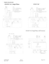
WIRING DIAGRAMS 120/220 VAC, Single Phase 12/24 VAC > 120/220 VAC Single Phase with Positioner EJMIOM.DOC Rev B May 5, 2005 ECR 930T Page 4 of 6 size="-3">
Open the catalog to page 4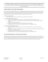
The two limit switches operating off the cams on the output shaft determine the exact positions where the actuator will stop at the end of each cycle. The first limit switch (lowest) determines the OPEN position (CCW rotation). The second limit switch (from bottom) determines the CLOSED position (CW rotation). The limit switches can be adjusted from5 to 320 degrees of actuator rotation. If an adjustment of any of the positions is required, proceed as follows: A. Remove Actuator Cover Remove the actuator cover by removing the screws securing the cover to the base. B. Adjust the OPEN limit switch...
Open the catalog to page 5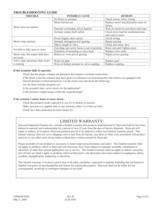
TROUBLE POSSIBLE CAUSE REMEDY No Power to actuator Check source, fuses, wiring Motor burned out Replace motor and determine cause of failure Motor does not operate Actuator output shaft stalled Check drive load for mechanical jam and correct cause Thermal overloaded, (Over heated) Wait for motor to cool down and reset. Power Supply short circuit Check wiring Motor stops running Object caught in valve Check and clean valve Jammed, damaged power gearing Repair gearing Not able to fully open or close Distortion of mounting or valve stem. Replace valve stem Traveling cam screw loose or out of position....
Open the catalog to page 6All Hayward Industries, Inc. catalogs and technical brochures
 NPP0412A - TB Series in GFPP
2 Pages
 Industrial Product Guide
164 Pages
 Hayward Condensed Product Guide
36 Pages
 Chemical Resistance Guide
13 Pages
 WPP-19 Corrosion-Resistant Pumps
20 Pages
 ACT-06 Actuation and Controls
32 Pages
 Solenoid Valves - IOM
4 Pages
 Pneumatic Actuator Model PCD/PCS
10 Pages
 Bag Filter - PVDF
2 Pages
 Bag Filter - PPL
2 Pages
 Duplex Basket Strainers
4 Pages
 Cartridge Filter
2 Pages
 Simplex Basket Strainers
2 Pages
 Duplex Bag Filter
2 Pages
 Y Strainers
2 Pages
 QIC Valves
2 Pages
 Y Check Valves
2 Pages
 Pressure Regulators
2 Pages
 Vacuum Breaker
2 Pages
 Needle Valves
1 Page
 Universal Stopcock
2 Pages
 Three Way True Union Valves
2 Pages
 Gauge Guards
2 Pages
 True Union Ball Check Valves
2 Pages
 Foot Valve Screens
1 Page
 Diaphragm Valves 3" to 6"
2 Pages
 Diaphragm Valves 1/2" to 2"
2 Pages
 Bulkhead Fittings
2 Pages
 Swing Check Valves
2 Pages
 Butterfly Valves 14" to 24"
2 Pages
 Relief Valves
2 Pages
 Angle Valves
2 Pages


