- Catalogs
- Hayward Industries, Inc.
- Bag Filter - PVDF
Bag Filter - PVDF

Bag Filter - PVDF
This document provides installation, operation, and maintenance instructions for the Hayward PVDF Bag Filter. It emphasizes the importance of following these guidelines to prevent injury and ensure proper functionality.
Warranty and Responsibility
Hayward guarantees its products against defects in material and workmanship but does not assume responsibility for damages or injuries due to improper installation, misuse, or chemical incompatibility. Users should verify compatibility and adhere to operating pressure and temperature limitations.
Installation Instructions
- Inspection: Inspect the bag filter upon receipt for any transit damage and report it immediately.
- Location and Support: Install the bag filter at least 24 inches downstream of a Hayward strainer and bolt it to the floor using the integral flange.
- Piping Installation: Use a 2” or 63 mm line from the strainer to the bag filter inlet and ensure proper valve and flange connections. Install a vent fitting on top with an O-ring.
Operation
- Operating Information: The bag filter is part of the Hayward filtration system, concentrating solids in a disposable bag while returning clean liquid to the process.
- System Startup: Follow a specific procedure to purge air and gradually apply pressure, ensuring all valves are correctly operated.
- Maintenance: Regularly remove collected solids and change the filter bag when the pressure differential reaches 15 PSIG. Follow a detailed procedure for safe bag replacement.
Specifications
- Maximum Working Pressure: 100 PSIG at 70ºF
- Maximum Working Temperature: 280ºF
- Maximum Flow: 100 GPM without bag
- Solids Collection Capacity: 25 pounds
- Inlet/Outlet/Drain: 2” Class 150 Flange
- Vent: 5/8”-11 UNC
- Filter Bag: 50 Micron, 7” x 32”
- Seals: Viton
Additional Notes
Direct installation of metal pipes into plastic connections is not recommended due to differential thermal expansion and other factors. Ensure proper system design to accommodate temperature effects and mechanical loading.
Catalog excerpts
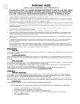
1. Hayward guarantees its products against defective material and workmanship only. Hayward assumes no responsibility for damage or injuries resulting from improper installation, misapplication, or abuse of any product. 2. Hayward assumes no responsibility for damage or injury resulting from chemical incompatibility between its products and the process fluids to which they are subjected. Compatibility charts provided in Hayward literature are based on ambient temperatures of 70F and are for reference only. Customer should always test to determine application suitability. 3. Consult Hayward literature to determine operating pressure and temperature limitations before installing any Hayward product. Note that the maximum recommended fluid velocity through any Hayward product is eight feet per second. Higher flow rates can result in possible damage due to the water hammer effect. Also note that maximum operating pressure is dependent upon material selection as well as operating temperature. 4. Hayward products are designed primarily for use with non-compressible liquids. They should NEVER be used or tested with compressible fluids such as compressed air or nitrogen. 5. Systems should always be depressurized and drained prior to installing or maintaining Hayward products. 6. Temperature effect on piping systems should always be considered when the systems are initially designed. Piping systems must be designed and supported to prevent excess mechanical loading on Hayward equipment due to system misalignment, weight, shock, vibration, and the effects of thermal expansion and contraction. 7. Because PVC and CPVC plastic products become brittle below 40F, Hayward recommends caution in their installation and use below this temperature. 8. Published operating torque requirements are based upon testing of new valves using clean water at 70F. Valve torque is affected by many factors including fluid chemistry, viscosity, flow rate, and temperature. These should be considered when sizing electric or pneumatic actuators. 9. Due to differential thermal expansion rates between metal and plastic, transmittal of pipe vibration, and pipe loading forces DIRECT INSTALLATION OF METAL PIPE INTO PLASTIC CONNECTIONS IS NOT RECOMMENDED. Wherever installation of plastic valves into metal piping systems is necessary, it is recommended that at least 10 pipe diameter in length of plastic pipe be installed upstream and downstream of the plastic valve to compensate for the factors mentioned above. > UPON RECEIPT OF THE BAG FILTER, INSPECT IT FOR DAMAGE THAT MIGHT HAVE OCCURRED DURING TRANSIT. REPORT ANY DAMAGE TO THE CARRIER IMMEDIATELY. > THE HAYWARD BAG FILTER SHOULD BE INSTALLED NOT LESS THAN 24 DOWN STREAM OF A HAYWARD STRAINER. THE BAG FILTER MUST BE BOLTED TO THE FLOOR TO INSURE PROPER PIPING INSTALLATION. A INTEGRAL FLANGE ON THE BASE OF THE BAG FILTER WILL ACCEPT 3/4Ԕ STUDS. > FROM THE HAYWARD STRAINER, A 2 OR 63 mm LINE IS REQUIRED TO THE INLET OF THE BAG FILTER. CONNECT A 2Ԕ CLASS 150 FLANGE TO A VALVE AND THEN TO THE UPPER 2 Class 150 FLANGE (INLET) OF THE BAG FILTER. A 2Ԕ OR 63mm LINE MUST BE PIPED FROM THE BAG FILTER 2 Class 150 FLANGE BOTTOM PORT (OUTLET) TO A DETERMINED SUCTION SOURCE (SYSTEM PUMP SUCTION). A VALVE IS REQUIRED ON THIS OUTLET LINE. IT IS RECOMMENDED THAT A 2Ԕ Class 150 FLANGED DRAIN VALVE BE INSTALLED ON THE UNUSED BOTTOM (DRAIN) PORT THE VENT FITTING MUST BE INSTALLED ON THE TOP OF THE UNIT. DO NOT FORGET THE O-RING. > THE HAYWARD PVDF BAG FILTER IS DESIGNED AS AN INTEGRAL PART OF THE HAYWARD FILTRATION-BAG FILTER SYSTEM. INSTALLED DOWN STREAM OF THE HAYWARD STRAINER, THE HAYWARD BAG FILTER CONCENTRATES THE SOLIDS, AND PROVIDES CONVENIENT, ECONOMICAL REMOVAL OF THE SOLIDS FROM THE PROCESS WITH VERY LOW LIQUID LOSS. LARGE SOLIDS ARE SEPARATED FROM THE LIQUID WITH THE HAYWARD STRAINER WHILE SMALLER SOLIDS ARE ACCUMULATED BY THE BAG FILTER . THE BAG FILTER CONCENTRATES THE SOLIDS IN A DISPOSABLE BAG, WHILE CLEAN LIQUID IS PIPED BACK TO THE PROCESS. > FOLLOW THE PROCEDURE BELOW FOR CHANGING THE BAG FOR INITIAL BAG INSTALLATION. > 1. CLOSE THE VALVE ON THE OUTLET OF THE BAG FILTER . 2. OPEN THE VENT LOCATED ON THE TOP OF THE BAG FILTER. 3. SLOWLY AND PARTIALLY OPEN THE VALVE ON THE INLET OF THE BAG FILTER. 4. CAREFULLY VENT ALL THE AIR FROM THE BAG FILTER. CLOSE THE VENT WHEN LIQUID BEGINS TO DISCHARGE. 5. FULLY OPEN THE INLET VALVE. 6. FULLY OPEN THE OUTLET VALVE. >
Open the catalog to page 1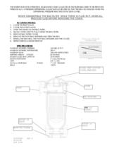
THE SYSTEM IS NOW IN OPERATION. SOLIDS WHICH ARE COLLECTED IN THE FILTER BAG NEED TO BE REMOVED PERIODICALLY. A PRESSURE DIFFERENTIAL GAUGE SHOULD BE USED SO THAT THE BAG IS CHANGED WHEN THE DIFFERENTIAL PRESSURE REACHES OR EXCEEDS 15 PSIG. > TO CHANGE THE BAG: 1. CLOSE THE INLET VALVE. 2. CLOSE THE OUTLET VALVE. 3. OPEN THE DRAIN ON THE BAG FILTER . 4. SLOWLY OPEN VENT TO FULLY DRAIN THE BAG FILTER. 5. REMOVE BAG FILTER COVER. 6. REMOVE THE PVDF BAG RETAINER AND THEN THE BAG 7. INSTALL THE NEW BAG, THE PVDF BAG RETAINER AND THE COVER. 8. REPEAT STEPS 3-6 UNDER START-UP > not recommended MAXIMUM...
Open the catalog to page 2All Hayward Industries, Inc. catalogs and technical brochures
 NPP0412A - TB Series in GFPP
2 Pages
 Industrial Product Guide
164 Pages
 Hayward Condensed Product Guide
36 Pages
 Chemical Resistance Guide
13 Pages
 WPP-19 Corrosion-Resistant Pumps
20 Pages
 ACT-06 Actuation and Controls
32 Pages
 Solenoid Valves - IOM
4 Pages
 Pneumatic Actuator Model PCD/PCS
10 Pages
 Electric Actuator Model EJM
6 Pages
 Bag Filter - PPL
2 Pages
 Duplex Basket Strainers
4 Pages
 Cartridge Filter
2 Pages
 Simplex Basket Strainers
2 Pages
 Duplex Bag Filter
2 Pages
 Y Strainers
2 Pages
 QIC Valves
2 Pages
 Y Check Valves
2 Pages
 Pressure Regulators
2 Pages
 Vacuum Breaker
2 Pages
 Needle Valves
1 Page
 Universal Stopcock
2 Pages
 Three Way True Union Valves
2 Pages
 Gauge Guards
2 Pages
 True Union Ball Check Valves
2 Pages
 Foot Valve Screens
1 Page
 Diaphragm Valves 3" to 6"
2 Pages
 Diaphragm Valves 1/2" to 2"
2 Pages
 Bulkhead Fittings
2 Pages
 Swing Check Valves
2 Pages
 Butterfly Valves 14" to 24"
2 Pages
 Relief Valves
2 Pages
 Angle Valves
2 Pages


