VP
1 /35Pages

VP
1 /35Pages
Catalog excerpts

Directional seated valve type VP Product documentation Directional seated valve, zero leakage Operating pressure pmax: Flow rate Qmax:
Open the catalog to page 1
© by HAWE Hydraulik SE. The reproduction and distribution of this document, as well as the use and communication of its contents to others without explicit authorization, is prohibited. Offenders will be held liable for the payment of damages. All rights reserved in the event of patent or utility model applications. Brand names, product names and trademarks are not specifically indicated. In particular with regard to registered and protected names and trademarks, usage is subject to legal provisions. HAWE Hydraulik respects these legal provisions in all cases. HAWE Hydraulik cannot provide individual...
Open the catalog to page 2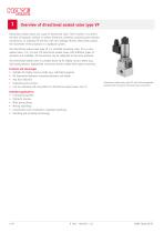
Overview of directional seated valve type VP Directional seated valves are a type of directional valve. Their function is to direct the ow of hydraulic medium in certain directions, therefore connecting the relevant connections, or shutting off the ow with zero leakage. By this means they control the movement of the actuators in a hydraulic system. The directional seated valve type VP is a manifold mounting valve. It is a coneseated valve. 2/2, 3/2 and 4/2 directional seated valves with different types of actuation are available. All connections can be subjected to the same pressures. The directional...
Open the catalog to page 4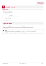
Available versions 2.3 "Connection block for pipe connection" 2.2 "Circuit symbols" 2.1 "Basic type and size" 2.1 Basic type and size Type Flow rate Qmax (lpm) NOTICE Operating pressures depend on the solenoid version, see Chapter 2.4.1, "Solenoid voltage and connectors" Specifications apply for hydraulic uids, see Chapter 3.1, "General data"
Open the catalog to page 5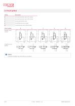
2.2 Circuit symbols Coding 2/2-way directional valve, N/C contact 2/2-way directional valve, N/O contact 4/2-directional valve, P-B/A-R open Circuit symbol detailed circuit symbols simplied circuit symbols NOTICE Coding W available only with electrical actuation.
Open the catalog to page 6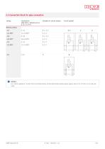
2.3 Connection block for pipe connection Coding Suitable for circuit symbol Circuit symbol Without coding NOTICE For circuit symbols R, S and Z the connection blocks of the directional seated valves type G size 12 to D 7300-12 can also be used.
Open the catalog to page 7
2.4 Actuation 2.4.1 Solenoid voltage and connectors Coding Electrical connection Pressure Nominal voltage pmax (bar) Protection Circuit class symbol (IEC 60529) Solenoid with interchangeable solenoid X(G)M 12 X(G)M 24 X(G)M 48 X(G)M 98 X(G)M 205 X(G)M 24/18W WGM 110 WGM 230 XM without connector GM with line connector LM with LED connector WGM with a rectifier circuit in the line connector L5KM with LED connector and moulded-on cable 5 m long, see D 7163 Explosion-proof solenoid in terminal box X 24 EX 55 FM Observe the electrical data for explosion-proof solenoids! An application-specic cable...
Open the catalog to page 8
Manual override Coding Circuit symbol Without coding with detent without detent, spring return mechanism Further technical data see Chapter 3.5.1, "Electrical data for a standard solenoid" 2.4.2 Further actuations Coding Main data Mechanical (sensing roller) Manual (sensing lever) Manual (rotary knob) Circuit symbol Further technical data, see Chapter 3.6, "Technical data - Further actuations"
Open the catalog to page 9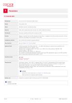
3.1 General data Designation 2/2, 3/2 and 4/2 directional seated valves Cone-seated valve Individual valve for manifold mounting Steel; electro-galvanised valve housing; zinc-nickel coated coil housing Base plate assembly without/with connection block Negative, transition from one ow direction to the other is completed only at the stroke end position. During switching, all passages are connected to each other. Installation position Any; vertical with actuation upwards preferred Flow direction Any, see Chapter 2.2, "Circuit symbols" Hydraulic uid Lubricating greases from NLGI grades 000 ......
Open the catalog to page 10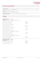
3.2 Pressure and volumetric ow Operating pressure pmax = 400 bar, 250 bar for the solenoid X 24 EX 55 FM and X(G)M 24/18W, all connections can withstand the full operating pressure. Flow rate Qmax = 15 lpm Values are for hydraulic uid Static overload capacity approx. 2x pmax, applies when the valve is in the rest position 3.3 Weight Valve complete with actuation Coding solenoid actuation XM, GM, LM R, S, Z G W mechanical sensing roller K / sensing pin T R, S, Z G manual sensing lever F / rotary knob D R, S, Z G Single connection block (without valve)
Open the catalog to page 11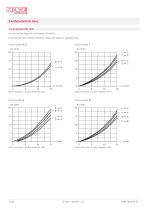
3.4 Characteristic lines Sp-Q characteristic lines Viscosity of the hydraulic uid approx. 60 mm2/s Characteristic lines indicate reference values and apply for hydraulic uid. Circuit symbol R, S
Open the catalog to page 12
3.5 Electrical data 3.5.1 Electrical data for a standard solenoid The solenoids are built and tested to DIN VDE 0580. Coding Nominal voltage Nominal voltage INFORMATION The electrical data for GM solenoids and WGM solenoids are reference values (max) and may vary slightly depending on the values stipulated by the manufacturer. Switching times Switching operations Approx. 2000/h, to be seen as approximately evenly distributed Insulation material class Contact temperature Contact temperature at 20°C, ambient temperature: approx. 85°C ... 95 °C (cladding). In adhering to the reference values for...
Open the catalog to page 13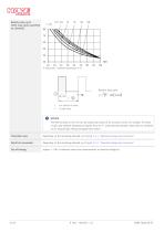
Relative duty cycle 100% duty cycle (specied on solenoid) % duty cycle; T ambient temperature (°C) Relative duty cycle t on (switch-on time) T (cycle time) NOTICE The thermal load on the coil can be reduced by means of an economy circuit, for example. For block circuits and ambient temperatures higher than 40 °C, avoid placing solenoid valves that are switched on for long periods directly alongside each other! Protection class Depending on the actuating solenoid see Chapter 2.4.1, "Solenoid voltage and connectors" Electrical connection Depending on the actuating solenoid see Chapter 2.4.1, "Solenoid...
Open the catalog to page 14
Circuit diagrams DC voltage NOTICE For other connectors, such as those with clamp diodes, economy circuits or LEDs, see D 7163
Open the catalog to page 15All HAWE Hydraulik SE catalogs and technical brochures
 Pressure switch type DG 2025
21 Pages
 VR
VR15 Pages
 BVE
BVE54 Pages
 SLC
SLC17 Pages
 BNG
BNG25 Pages
 BA
BA45 Pages
 VB
VB88 Pages
 VH
VH6 Pages
 SL1
SL115 Pages
 ROLV
ROLV23 Pages
 EM
EM41 Pages
 PS
PS20 Pages
 K60N
K60N19 Pages
 V30D
V30D60 Pages
 V80M
V80M30 Pages
 V30E
V30E51 Pages
 RZ
RZ12 Pages
 Radial piston pump type R, RG
23 Pages
 C40V
C40V47 Pages
 Mini hydraulic power pack type A
23 Pages
 HR 080
17 Pages
 HICON
HICON14 Pages
 INKA
INKA35 Pages
 FXU
FXU35 Pages
 V60N
V60N71 Pages
 Product catalogue
299 Pages


