- Catalogs
- HAWE Hydraulik SE
- Valve banks type BWN and BWH
- Company
- Products
- Catalogs
- News & Trends
- Exhibitions
Valve banks type BWN and BWH
1 /23Pages

Valve banks type BWN and BWH
1 /23Pages
Catalog excerpts

Valve banks type BWN and BWH with directional valves acc. to D 7470 A/1 Pressure pmax = 350 ... 450 bar Flow Qmax = 5 ... 30 lpm General information The directional valves WN 1 or WH 1(2 and 3) type (acc. to D 7470 A/1) are mounted on sub-plates. These valve banks are laterally arranged between a connection block and an end plate, all held together and hydraulically connected via a tie rod. The connection block, with inlet for pressurised oil and outlet for the return, is available in differing versions: With/without pressure limiting valve or as an adapter to mount the valve bank on hydraulic power units. The galleries for pressurised oil and return run through all sub-plates and connect the mounted valves in parallel. The valves are counted starting from the connection block. For more detailed data and notes concerning the individual valves refer to D 7470 A/1. Directional valve bank into basic version Order example and flow pattern symbol corresponding to the photo BWN 1 A - 2/120 - FNGS - 1 - 1 - G 24 Connection block Directional valve Directional valve bank for direct mounting at a compact hydraulic power pack Here e.g. HK 44/1 M - H 6,0 - A1/200 (acc. to D 7600-4) Order example and flow pattern symbol corresponding to the photo HK 44/1 M - H 6,0 - A1/200 - BWN 2 F - FHH - 1 - 1 - G 24 Order coding of the pump Directional valve bank Compact hydraulic power pack Directional valve bank HAWE Hydraulik SE STREITFELDSTR. 25 • 81673 MÜNCHEN © 1985 by HAWE Hydraulik
Open the catalog to page 1
Available versions For complete type overview ref. to section 7, page 23 Type coding and general parameter Order examples: Connection block or adapter plate (section 2.2) End plate (sect. 2.3) Directional valves (section 2.4 ++) Desired pressure setting (bar) Table 1: Basic type Table 2: Port size Valves acc. to Pressure D 7470 A/1 pmax (bar) Directional valve bank Table 3: Actuation solenoid For further voltage and notes ref. to see D 7470 A/1 sect. 2.2.2 Connection blocks and adapter plates Suited for For installation into the piping system. Use port R always as reflow (pR < 20 bar) Adjustable...
Open the catalog to page 2
Notes (DG stands for pressure switch) With drain valve, e.g. to discharge a connected accumulator (see sect. 5.5) For type BWN(H) 1 and BWH 2: With pressure switch acc. to D 5440 for monitoring the P duct 1.DG 2.DG .2 /2 = Without pressure switch, but retrofitting is possible (only with coding 4. and 5.) .3 /33 = DG 33 Adjustm. range: 200 ... (700) bar .4 /34 = DG 34 100 ... 400 bar .5 /35 = DG 35 40 ... 250 bar /36 = DG 36 4 ... 12 bar .6 .65 /65 = DG 365 12 ... 170 bar Coding 4./.. For type BWN(H) 1: With additional drain valve ( ref. to coding 2 ) and port for pressure gauge connection G 1/4...
Open the catalog to page 3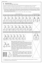
Directional valves Diretional valves type BWN 1 (basic function) o Coding of the available flow pattern symbols (individual directional valve with corresponding sub-plate = valve section) 1) o Maximum 10 valves can be combined; Flow pattern symbols J, U, V, L, K, G, and GX are to be counted as 2 valves. o Idle circulation valves D, F or A should be placed as first valve within the valve bank (first valve coding) to minimize the back pressure. o Directional valve banks slightly reduce the heat dissipation to the surrounding because of the small distance between neighboring valve solenoids. It...
Open the catalog to page 4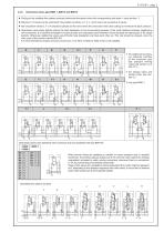
Directional valves type BWH 1, BWH 2 and BWH 3 o Coding of the available flow pattern symbols (individual directional valve with corresponding sub-plate = valve section) 1) o Maximum 10 valves can be combined; Flow pattern symbols J, U, V, L, and K are to be counted as 2 valves. o Idle circulation valves D, F or A should be placed as first valve within the valve bank (first valve coding) to minimize the back pressure. o Directional valve banks slightly reduce the heat dissipation to the surrounding because of the small distance between neighboring valve solenoids. It is therefore advisable to...
Open the catalog to page 5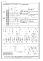
Directional valves with integrated additional elements Pressure switches (DG 33, DG 34, DG 35, DG 36 oder DG 365 nach D 5440) at ports A, B, and P Not available for directional spool valves coding W(WX) and G(GX) acc. to sect. 2.4.1! Adjustment range Mounted pressure switch Coding Position Suited for 3/2-way directional valve with one DG at port A: BWN1A-H4-1-1-G 24 Can’t be combined with directional seated valves, coding D, A, F, P, O, I, Y, S, T or valve banks BWN(H)..C (D, S, L) as well as 1. valve within valve bank BWN(H) 1(2) P! 3/2-way directional valve with return pressure stop and one...
Open the catalog to page 6
Version with pressure limiting valve and pressure switch at port A (only for type BWN 1 and BWH 1) For technical data of the pressure limiting valve type MVF 4.., see D 7000 E/1 or for the pressure switch type DG.., see D 5440 Order example: Basic type coding acc. to section 2 ++ 3/3-way directional seated valve (acc. to sect. 2.4.1 and 2.4.2) with directly mounted pressure limiting valve and pressure switch: J2 (3, 4, 5, 36, 65) /... U2 (3, 4, 5, 36, 65) /... V2 (3, 4, 5, 36, 65) /... Symbols (examples) Pressure specification (bar) for the pressure limiting valve Attention: Not available in...
Open the catalog to page 7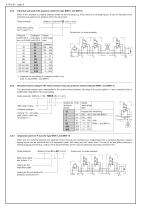
Individual sub-plate with pressure switch (for type BWN 1 and BWH 1) When it isn‘t possible to install a pressure switch at the end plate e.g. when there is not enough space, it can be mounted on an individual sub-plate at any position within the valve bank. BWN1A-1/200-HM-33-H-42-1-G 24 Order example: Basic type coding acc. to sect. 2 ++ Symbol acc. to order example Pressure Coding for Adjustswitch DG 3. sub-plate ment range acc. to D 5440 with DG 3. (bar) 33 34 35 36 364 365 DG 5 E-250 DG 5 E-400 DG 5 E-600 1) Prepared for retrofitting of a pressure switch, only avail. for type BWN 1 and BWH...
Open the catalog to page 8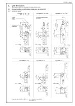
Unit dimensions All dimensions are in mm, are subject to change without notice! Connection blocks and adapter plates acc. to section 2.2 For missing specifications see below! Provision for a lead seal Ports ISO 228/1 (BSPP): A, B, P, R = G 1/4 (BWN(H) 1 and BWH 2) G 3/8 (BWH 3)
Open the catalog to page 9All HAWE Hydraulik SE catalogs and technical brochures
 Pressure switch type DG 2025
21 Pages
 VR
VR15 Pages
 BVE
BVE54 Pages
 SLC
SLC17 Pages
 BNG
BNG25 Pages
 BA
BA45 Pages
 VB
VB88 Pages
 VP
VP35 Pages
 VH
VH6 Pages
 SL1
SL115 Pages
 ROLV
ROLV23 Pages
 EM
EM41 Pages
 PS
PS20 Pages
 K60N
K60N19 Pages
 V30D
V30D60 Pages
 V80M
V80M30 Pages
 V30E
V30E51 Pages
 RZ
RZ12 Pages
 Radial piston pump type R, RG
23 Pages
 C40V
C40V47 Pages
 Mini hydraulic power pack type A
23 Pages
 HR 080
17 Pages
 HICON
HICON14 Pages
 INKA
INKA35 Pages
 FXU
FXU35 Pages
 V60N
V60N71 Pages
 Product catalogue
299 Pages


