- Catalogs
- HAWE Hydraulik SE
- Valve bank (directional spool valve) type CWS
Valve bank (directional spool valve) type CWS
1 /42Pages

Valve bank (directional spool valve) type CWS
1 /42Pages
Catalog excerpts

Valve bank (directional spool valve) type CWS Product documentation Series connection Operating pressure pmax: Flow rate Qmax:
Open the catalog to page 1
© by HAWE Hydraulik SE. The reproduction and distribution of this document, as well as the use and communication of its contents to others without explicit authorization, is prohibited. Offenders will be held liable for the payment of damages. All rights reserved in the event of patent or utility model applications. Brand names, product names and trademarks are not specifically indicated. In particular with regard to registered and protected names and trademarks, usage is subject to legal provisions. HAWE Hydraulik respects these legal provisions in all cases. HAWE Hydraulik cannot provide individual...
Open the catalog to page 2
Overview Valve bank (directional spool valve) type CWS Directional spool valves are a type of directional valve. They control the direction of movement and the velocity of single and double-acting hydraulic consumers. The directional spool valve type CWS is directly actuated and has binary (open/ closed) activation. Multiple directional valves can be combined in series in the valve bank type CWS. A range of connection blocks and mounted blocks offer additional options for a wide range of applications. The valve bank CWS is used mainly in mobile hydraulics. In stationary hydraulics, the direct...
Open the catalog to page 4
Connection block Valve section Ancillary block End plate
Open the catalog to page 5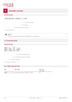
Available versions 2.4 "End plate" 2.2 "Directional valve section" 2.1 "Connection block" NOTICE A maximum of 10 valve sections can be combined in one valve bank. 2.1 Connection block Ordering example CWS 2 CWS 2 CWS 2 2.1.3 "Connection block basic types" 2.1.2 "Material and ports" 2.1.1 "Basic type and size" 2.1.1 Basic type and size Type Flow rate Qmax (lpm) Directional spool valve type CWS 2, size 2
Open the catalog to page 6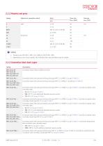
2.1.2 Material and ports Coding Material of connection block Flow rate Qmax (lpm) Thread as per ISO 228-1, SAE J 514 (UNF) or JIS B 2351 (JIS) Depending on the circuit symbol, the individual ow rate permitted may be smaller. 2.1.3 Connection block basic types Coding Connection block without additional valves Connection block with pressure-limiting valve type MVF 5 C or MVB 5 C as per D 7000 E/1 Connection block with pressure-limiting valve type MVF 6 C or MVB 6 C according to D 7000 E/1 Connection block with pressure-limiting valve type MVF 5 C or MVB 5 C as per D 7000 E/1 and idle circulation...
Open the catalog to page 7
CWS 2(L)3 SP6/… Connection block with pressure-limiting valve type MVF 6 C or MVB 6 C as per D 7000 E/1 and electro-proportional CWS 2(L) UNF3 SP6/… idle circulation valve (normally open). CWS 2(L) JIS3 SP6/… ■ SP6: EMP 31 S as per D 7490/1 ■ SPB6: EMP 31 S with additional detented manual override CWS 2(L)3 VP6/… Connection block with pressure-limiting valve type MVF 6 C or MVB 6 C as per D 7000 E/1 and electro proportional CWS 2(L) UNF3 VP6/… idle circulation valve (normally closed) type EMP 31 V as per D 7490/1 CWS 2(L) JIS3 VP6/… CWS 2L4(H)(R)6/…-.. Connection block with pressure-limiting...
Open the catalog to page 8
2.1.4 Pressure-limiting valve Coding Standard pressure-limiting valve (type MVF 5 C or MVF 6 C as per D 7000 E/1) Max. permissible return pressure pR = 20 bar (adjustment range 50 to 315 bar) Pressure-limiting valve for increased return pressure (type MVF 5 C or MVB 6 C as per D 7000 E/1) Max. permissible return pressure pR = 200 bar (adjustment range 50 to 315 bar)
Open the catalog to page 9
2.2 Directional valve section The directional valve section is available either with integrated threads for the consumer ports A and B, or with a ange surface for mounting an ancillary block (see Chapter 2.2.7, "Ancillary block") or an intermediate plate (see Chapter 2.2.8, "Intermediate plate"). Valve section with integrated threads with ancillary block with intermediate plate and ancillary block 2.5 "Solenoid version" 3.5 "Electrical data" 2.4 "End plate" 2.2.6 "Seal of consumer ports" 2.2.7 "Ancillary block" 2.2.5 "Additional functions" 2.2.4 "Hand lever" 2.2.3 "Actuation" 2.2.1 "Circuit...
Open the catalog to page 10
2.2.1 Circuit symbol 4/3 directional spool valve G 4/2 directional spool valve 3/3 directional spool valve X NOTICE Circuit symbol X is only possible in conjunction with electrical and manual actuation, e.g. MHA (see Chapter 2.2.3, "Actuation" and Chapter 2.2.4, "Hand lever")
Open the catalog to page 11
2.2.2 Flow rate For CWS sections with proportional actuation (see Chapter 2.2.3, "Actuation"), the spools’ meter-in edges are available in the four nominal sizes listed below: Coding Flow rate QA/B (lpm) at maximum spool valve elevation and at pressure difference of 9 bar NOTICE The valve spool sizes are designed so that in practice the actual ow rate is slightly higher. Depending on the position of the valve section in the manifold, and especially at high ow rates and resulting pressure losses in the manifold, the ow rate may fall below the nominal value. HAWE Hydraul
Open the catalog to page 12
2.2.3 Actuation On-off actuation Coding Combination options Electrical actuation. Plug position inside on the spool block and upwards in the direction of the consumer ports (standard version). MT Electrical actuation with manual override. the solenoid version DT (see Chapter 2.5, "Solenoid version") and the ancillary blocks coding /(L)2CH, /(L)2CHA, /(L)CHB (see Chapter 2.2.7) Plug position inside on the spool block and upwards in the direction of the consumer ports (standard version). Only in conjunction with Plug position outside and upwards in the direction of the consumer ports. MT1 two additional...
Open the catalog to page 13
Electro-proportional actuation Coding Combination options Electro-proportional actuation Plug position inside on the spool block and upwards in the direction of the consumer ports (standard version) a) the solenoid version DT (see Chapter 2.5, "Solenoid version") and b) the ancillary blocks with coding /(L)2CH, /(L)2CHA and /(L)CHB, (see Chapter 2.2.7) requires two additional spacer plates with coding /ZC11 (see Chapter 2.2.8, "Intermediate plate") to prevent collision of magnetic plug with ancillary block. Electro-proportional actuation Electro-proportional actuation with manual override Plug...
Open the catalog to page 14All HAWE Hydraulik SE catalogs and technical brochures
 Pressure switch type DG 2025
21 Pages
 VR
VR15 Pages
 BVE
BVE54 Pages
 SLC
SLC17 Pages
 BNG
BNG25 Pages
 BA
BA45 Pages
 VB
VB88 Pages
 VP
VP35 Pages
 VH
VH6 Pages
 SL1
SL115 Pages
 ROLV
ROLV23 Pages
 EM
EM41 Pages
 PS
PS20 Pages
 K60N
K60N19 Pages
 V30D
V30D60 Pages
 V80M
V80M30 Pages
 V30E
V30E51 Pages
 RZ
RZ12 Pages
 Radial piston pump type R, RG
23 Pages
 C40V
C40V47 Pages
 Mini hydraulic power pack type A
23 Pages
 HR 080
17 Pages
 HICON
HICON14 Pages
 INKA
INKA35 Pages
 FXU
FXU35 Pages
 V60N
V60N71 Pages
 Product catalogue
299 Pages


