V30E
1 /51Pages

V30E
1 /51Pages
Catalog excerpts

Variable displacement axial piston pump type V30E Product documentation Open circuit Nominal pressure pnom max: Peak pressure pmax: Displacement volume Vmax:
Open the catalog to page 1
© by HAWE Hydraulik SE. The reproduction and distribution of this document as well as the use and communication of its contents to others without explicit authorization is prohibited. Offenders will be held liable for the payment of damages. All rights reserved in the event of patent or utility model applications. Brand names, product names and trademarks are not specifically indicated. In particular with regard to registered and protected names and trademarks, usage is subject to legal provisions. HAWE Hydraulik respects these legal provisions in all cases. HAWE Hydraulik cannot provide individual...
Open the catalog to page 2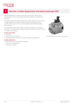
Overview: variable displacement axial piston pump type V30E Variable displacement axial piston pumps adjust the geometric output volume from maximum to zero. As a result they vary the ow rate that is provided to the consumers. The variable displacement axial piston pump type V30E is designed for open circuits in mobile hydraulics and operates according to the swash plate principle. It is available with the option of a thru-shaft for operating with additional hydraulic pumps in series. The sturdy pump is particularly suitable for continuous operation in challenging applications. The range of...
Open the catalog to page 4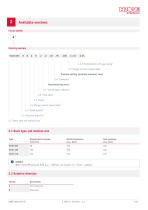
Available versions Circuit symbol -Z 05 4.4.2 "Combination with gear pump" 2.9 "Flange version (output side)" Pressure setting (nominal pressure) (bar) 2.8 "Controller" Manufacturing series 2.7 "Swivel angle indicator" 2.6 "Thru-shaft" 2.5 "Seals" 2.4 "Flange version (input side)" 2.3 "Shaft journal" 2.2 "Rotation direction" 2.1 "Basic type and nominal size" 2.1 Basic type and nominal size Type Nominal pressure pnom (bar) Peak pressure pmax (bar) NOTICE When using HFC pressure uid pmax = 300 bar, see Chapter 2.5, "Seals", coding C. 2.2 Rotation direction Coding
Open the catalog to page 5
2.3 Shaft journal Coding Spline shaft Spline shaft Spline shaft NOTICE Coding K: For a pressure setting of over 300 bar, a power controller must be used. 2.4 Flange version (input side) Coding NBR, suitable for HFC, for restrictions see Chapter 5, "Installation, operation and maintenance information"
Open the catalog to page 6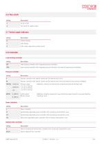
Thru-shaft for tandem pump 2.7 Swivel angle indicator Coding without display with display with swivel angle pick-up (Hall sensor) 2.8 Controller Load-sensing controller Coding Load-sensing controller with integrated pressure limitation Load-sensing controller with integrated pressure limitation and external pump pressure feedback Pressure controller Coding Pressure controller with remote-control port for external pilot valve Pressure controller with remote-control port for external pilot valve and external pump pressure feedback Additional, directly mounted electro proportional pressure-limiting...
Open the catalog to page 7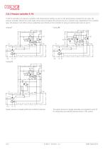
2.8.1 Pressure controller P, Pb P-and Pb-controllers are pressure controllers with xed pressure setting. As soon as the pump pressure exceeds the set value, the pressure controller reduces the swivel angle of the pump and adjusts the pressure level to a constant value. Depending on the controller type, the pressure is set either using an adjusting screw directly on the controller or using an external pilot valve on port X. Coding P System pressure is tapped within the controller (internal). The system pressure is tapped externally and signalled to port X2 to compensate any potential pressure...
Open the catalog to page 8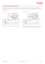
2.8.2 Load-sensing controller LSP, LSPb The LSP and LSPb controllers are ow controllers that generate a variable, speed-independent ow rate. The controller adapts the displacement volume of the pump to the required ow rate of the consumer and regulates a constant difference between load pressure and pump pressure. Coding LSP Coding LSPb System pressure is tapped within the controller (internal). The system pressure is tapped externally and signalled to port X2 to compensate any potential pressure losses in the system.
Open the catalog to page 9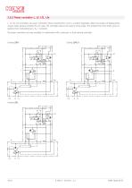
2.8.3 Power controller L, Lf, Lf1, Lfe L, Lf, Lf1, Lfe controllers are power controllers whose characteristic curve is a perfect hyperbola. When the product of displacement volume times pressure exceeds the set value, the controller reduces the pump’s swivel angle. This protects the drive shaft, motor or gearbox from overloading (pB x Vg = constant). The power controllers are only available in combination with a pressure- or load-sensing controller. Coding LSPLf Coding LSPL
Open the catalog to page 10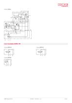
Coding LSPLfe 2.8.4 Controller BVPM, PM Coding BVPM1R
Open the catalog to page 11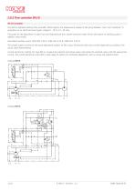
2.8.5 Flow controller EM.CH EM.CH controller The electro-hydraulic delivery ow controller EM.CH adjusts the displacement volume of the pump between "zero" and "maximum" in proportion to an electrical input signal, (target 0 - 10 V or 0 - 20 mA). The power for the adjustment is taken from the high-pressure line. System pressures under 50 bar will require an auxiliary pump in addition (thru-shaft). Associated auxiliary pump: V30E-09S: Z 02-6, V30E-160: Z 02-8, V30E-270: Z 02-11 The control system consists of the pump adjustment system, an NG 6 prop. directional valve and a swivel angle pick-up...
Open the catalog to page 12
Coding EMPLCH NOTICE The adjustment times are approx. 200 ms. The EM.CH controller can be combined with pressure, LS and/or power controllers to limit pressure and/or power. NOTICE Additional, separately laid out overpressure protection (pressure-limiting valve) must be included in the hydraulics circuit in order to prevent pressure peaks. Ordering example Version without pressure limitation and power controller: V30E-160 Version with pressure and power controller: V30E-270
Open the catalog to page 13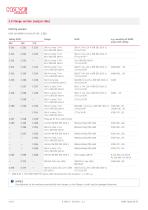
2.9 Flange version (output side) Ordering example: V30E-160 RDGN-2-0-04/LSP-350- C 222 Coding V30E e.g. mounting of HAWE pump with coding Prepared for thru-shaft (cover) ANSI B 92.1, FLAT ROOT SIDE FIT spline width deviating from the standard, s = 2.357-0.03 NOTICE Pay attention to the maximum permissible drive torque, as the ange or shaft may be damaged otherwise.
Open the catalog to page 14All HAWE Hydraulik SE catalogs and technical brochures
 Pressure switch type DG 2025
21 Pages
 VR
VR15 Pages
 BVE
BVE54 Pages
 SLC
SLC17 Pages
 BNG
BNG25 Pages
 BA
BA45 Pages
 VB
VB88 Pages
 VP
VP35 Pages
 VH
VH6 Pages
 SL1
SL115 Pages
 ROLV
ROLV23 Pages
 EM
EM41 Pages
 PS
PS20 Pages
 K60N
K60N19 Pages
 V30D
V30D60 Pages
 V80M
V80M30 Pages
 RZ
RZ12 Pages
 Radial piston pump type R, RG
23 Pages
 C40V
C40V47 Pages
 Mini hydraulic power pack type A
23 Pages
 HR 080
17 Pages
 HICON
HICON14 Pages
 INKA
INKA35 Pages
 FXU
FXU35 Pages
 V60N
V60N71 Pages
 Product catalogue
299 Pages


