SWS
1 /12Pages

SWS
1 /12Pages
Catalog excerpts

Directly solenoid actuated (on/off or proportional) = 25 lpm Flow Qmax Operation pressure pmax = 315 bar Directional spool valve banks type SWS General information The directional valve banks type SWS are a refined version of type SWR. Basic function is the directional control of hydraulic consumers (cylinders, motors). But this new concept enables also the incorporation of additional functions for each individual valve section on both the pump (check or throttle valves) and the consumer side (over-center, shock, or check valves). The actuation is carried out via pressure tight, single acting solenoids which act directly on the valve spool. A variety of connection blocks (featuring pressure and return ports) as well as end plates offer solutions to many applications. Order examples Example 1: Combination with compacthydraulic power pack Example 2: Valve bank with proportional-flow control valve in the connection block Example 3: Lifting module for reach trucks Hydraulic circuit and illustration acc. to example 1 HAWE HYDRAULIK SE STREITFELDSTR. 25 • 81673 MÜNCHEN D 7951 Directional spool valve banks type SWS March 1999-02
Open the catalog to page 1
Type coding key, overview Order example: Pressure setting (bar) Solenoid voltage (see section 4.2) End plates (see table 2) Ancillary blocks, additional functions on the consumer side (see table 7) /01, /02 Without ancillary block (A, B = G 1/4 or G 3/8) Ancillary block (A, B = G 1/4 or G 3/8) no additional functions Shock valve at A and B (G 3/8) with pressure setting Shock and suction valve at A and B (G 3/8) with pressure setting Shock and suction valve at A (G 3/8) with pressure setting Over-center valve at A and B (G 3/8) with pressure setting Over-center valve at A (G 3/8) with pressure...
Open the catalog to page 2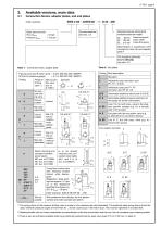
Available versions, main data Connection blocks, adapter plates, and end plates SWS 2 A6 - G/M/0/02 - 1 - G 24 - 200 Order example: Desired pressure setting (bar) available pressure ranges: (0) ... 80 bar Pressure specifi(0) ... 160 bar cation deter(0) ... 315 bar mines the spring For valve sections see sect. 3.2 Basic type and size Flow Qmax = 25 lpm Pressure pmax = 315 bar Specification is superfluous with connection block A5 and adapter plate F For actuation solenoids G 12 to WG 230, see sect. 4.2 Table 2: End plates Table 1: Connection block, adapter plate P (pump port) and R (return port)...
Open the catalog to page 3
Valve sections Directional spool valves Order example: SWS2 A6 - G /M /0 /02 - D06 /MP/DW /2AS180 BS180 - 1 -G24 - 200 Additional functions on the consumer side (table 7) Additional functions on the consumer side (table 7) For basic type, size, actuation solenoid, end plate, and pressure setting, see sect. 3.1 Solenoid version (table 5) Flow pattern symbol (table 3 and 4) Additional functions on the pump side (table 6) Table 3: Flow pattern symbols Additional functions on the pump side (table 6) Table 5: Solenoid version Flow pattern symbols Flow Attention: Only in connection with coding /MP...
Open the catalog to page 4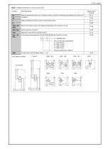
D 7951 page 5 Table 7: Additional functions on the consumer side Tapped ports A and B Brief description Without additional function (no connection block), cannot be combined with additional functions acc. to table 6 Without additional function, ports in the ancillary block Shock and suction valve, with pressure specification for A and B or A only Sequence valve for the consumer port A Over-center valve (example: /2AL4C200 BL4B180) for A and B or A only 4 = Release ration Valve version (flow dependent) A = appr. 20 lpm B = appr. 14 lpm C = appr. 10 lpm D = appr. 6 lpm Pressure setting max. 380...
Open the catalog to page 5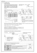
Intermediate sections Pressure reducing valve The valve can be ordered anywhere between the directional spool valve sections. All subsequent spool valve sections receive only pressure fluid with the set pressure (secondary pressure), independent of the higher system pressure upstream. Coding Z1 ... Z8 may be added any position within the complete valve bank coding, see order example in the margin. Order example and flow pattern symbol Table 8: Pressure reducing valve Adjustable pressure range 1) from ... to (bar) Tool adjustable Manually adjustable , -10 ... -15% of the pressure setting depending...
Open the catalog to page 6
General and hydraulic data Design Directional spool valve Surface protection Spool valve housing nitrous hardened, solenoid zinc galvanized Installed position Any, for fastening see dimensional drawings in section 5.1 ++ Pipe connection Pipe thread DIN ISO 228/1 (BSPP) Port coding Flow direction In accordance with arrow direction in the flow pattern symbols; It is not permissible to reverse the flow direction ! Pressurized fluid inlet port (pump) G 3/8 Consumer G 3/8 or G 1/4 (dep. on type) Return port G 3/8 Port for pressure gauge G 1/4 Over lapping Operation pressure Flow Qmax = 25 lpm; Permissible...
Open the catalog to page 7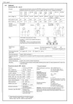
Solenoid Electrical data (/M... table 5) Solenoid Manufactured and tested conforming VDE 0580, operating pressure resistant in the pressure fluid Reference value for nom. power PN , 24.4 W * approx. 6% dep. on nom. voltage UN and brand Circuitry (valid for solenoid a and b) Coding G (...V DC) is only available with gray or black plugs Coding WG (..V AC) is only available with black plug, featuring an internal bridge rectifier circuit Relative duty cycle Gray plug Black plug At ambient temperature (°C) < 40 60 Duty cycle (%) Switching times (reference value) Switching operations Solenoid IP 54,...
Open the catalog to page 8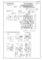
Unit dimensions Ancillary block (sect. 5.3) All dimensions in mm, subject to change without notice ! Connection block (sect. 5.1) End plate (sect. 5.3) Directional spool valve Double solenoid Coding /MM Solenoid (ex-proof version) Coding G 24 ex Manual emergency actuation Connection blocks and adapter plates (tool adjustable) (manually adjustable) Provision for a lead seal
Open the catalog to page 9
M 6, 6 deep Connection block directly mounted onto the pump Ports DIN ISO 228/1 (BSPP): A, P and R = G 3/8 with coding 2, 25 E, 21 E(P) and 31 E(P) P1, P2, R1 = G 1/2 with coding 3 Ports P and R are blocked with tapped plugs for 31 E(EP) M = Port for pressure gauge G 3/8
Open the catalog to page 10All HAWE Hydraulik SE catalogs and technical brochures
 Pressure switch type DG 2025
21 Pages
 VR
VR15 Pages
 BVE
BVE54 Pages
 SLC
SLC17 Pages
 BNG
BNG25 Pages
 BA
BA45 Pages
 VB
VB88 Pages
 VP
VP35 Pages
 VH
VH6 Pages
 SL1
SL115 Pages
 ROLV
ROLV23 Pages
 EM
EM41 Pages
 PS
PS20 Pages
 K60N
K60N19 Pages
 V30D
V30D60 Pages
 V80M
V80M30 Pages
 V30E
V30E51 Pages
 RZ
RZ12 Pages
 Radial piston pump type R, RG
23 Pages
 C40V
C40V47 Pages
 Mini hydraulic power pack type A
23 Pages
 HR 080
17 Pages
 HICON
HICON14 Pages
 INKA
INKA35 Pages
 FXU
FXU35 Pages
 V60N
V60N71 Pages
 Product catalogue
299 Pages


