SMD
1 /15Pages

SMD
1 /15Pages
Catalog excerpts
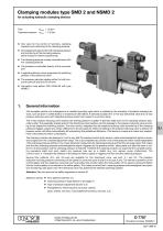
Clamping modules type SMD 2 and NSMD 2 for actuating hydraulic clamping devices Flow Operation pressure ' One valve for the control of functions, clamping pressure and monitoring of the clamping pressure ' One adjustment element for both clamping pressure and monitoring of the clamping pressure (either manual or electro-proportional) ' The clamping pressure is safely controlled even with low clamping pressure ' The pressure is controlled directly at the consumer port ' A special protective circuit supervises the switching position of the directional valve ' The pressure reduction applies either for both consumer ports (A and B) or for (A) only ' Connection hole pattern DIN 24340-A6 with type NSMD 2 General information This complete control unit is designed as a manifold mounting valve which is suitable for the actuation of hydraulic clamping devices, such as draw-in collets (hollow or massive) at CNC-lathes. A solenoid actuated 4/3- or 4/2-way directional valve and a 3-way pressure reducing valve with integrated pressure switch are housed in a common body. The 3-way pressure reducing valve reduces the existing pressure in gallery P (primary side) down to the clamping pressure (secondary side). The especially shaped spool of the directional valve creates a control passage to the pressure reducing valve according to the respective switching position. The micro switch integrated into the pressure reducing valve (monitoring of the clamping pressure) triggers a signal at a certain difference to the set pressure. When the setting of the pressure reducing valve is altered, the pressure switch will follow automatically still maintaining this predefined difference. This feature is unique and makes any readjustment of the pressure switch unnecessary. The clamping module was designed in such a way that the pressure switch gives always a clear acknowledgment signal or supervisory signal over the complete adjustment range. This is accomplished by a switch-over of the pressure switch mode independent of the clamping pressure setting. In the lower adjustment range both the clamping pressure and the flow are supervised. This makes sure that the (clamping pressure acknowledgment) signal, triggered by the pressure switch, takes place only after the draw-in collet is in its final position and the clamping pressure is reached. Therefore the clamping module can supervise the complete clamping procedure (start and end), detect any pressure loss due to a defect (e.g. line rupture, pump malfunction). The curves in sect. 4.1 illustrate the relations of the pressure where a signal is triggered, the flow and the clamping pressure Several flow patterns (4/3- and 4/2-way) are available for this directional valve, see sect. 3.1 and 3.2. The pressure reduction including pressure monitoring can be opted for consumer ports A and B or for port A only. The internal connection of the control gallery and the respective consumer port is provided only shortly before the final position of the spool is achieved. Before this the control gallery is connected to the reflow gallery. This makes sure that both, clamping pressure acknowledgment and pressure monitoring, take place only if the directional valve has achieved the selected switching position. Attention: Take into account the safety regulations in section 6! Selection criteria: ' ' ' ' Flow patternsl (section 3.1) Clamping pressure range (section 2 and page 7) Type of pressure adjustment (section 3.2) Possibilities for influencing the consumer velocity (avail. orifices, see sect. 2 and additional functions, see sect. 3.3) HAWE HYDRAULIK SE STREITFELDSTR. 25 • 81673 MÜNCHEN D 7787 Clamping modules (N)SMD 2 April 1998-01
Open the catalog to page 1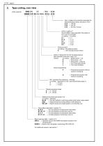
Type coding, over view Order example: Nom. voltage of the actuation solenoids (for directional spool valves, see also D 7451) G 12 = 12V DC G 24 = 24V DC X 24 = 24V DC, no plug Orifice in gallery P (flow limitation, being required if the system is fed via an accumulator) no coding = no orifice B1 = #1 B 1,5 = # 1.5 B2 = # 2.0 B 2,5 = # 2.5 B3 = # 3.0 Pressure switch no coding= No pressure switch K = with tracked pressure switch Means of adjustment for the clamping pressure (also see table 3a and 3b in sect. 3.2) manual: no coding = Slotted screw + nut D = Wing screw + nut R = Wing screw + wing...
Open the catalog to page 2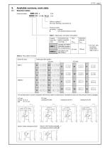
Available versions, main data Selection tables Order examples: Orifice in gallery P (For avail. diameter, see section 2) Pressure switch no coding = without K = with tracked pressure switch Table 1: Basic type, connection hole pattern Coding (type and size) Connection hole pattern (manifold mounting) 1) standard with HAWE hole pattern (superior flow characteristic) Operation pressure pmax hole pattern conf. DIN 24340-A For nom. size, see dimensional drawings in sect. 5 Table 2: Flow pattern symbols Suited for type Coding and flow pattern 4/2-way The symbols below must be completed with the flow...
Open the catalog to page 3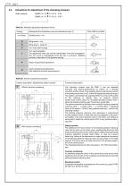
Actuations for adjustment of the clamping pressure Order example Table 3a: Manually adjustable adjustment device Coding no coding Description (for illustrations, see unit dimensions sect. 5) Flow pattern symbols Wing screw + wing nut Turn knob (self-locking) Turn knob (lockable) The adjustment knob can only be manipulated, if the key is plugged in. The turn knob is disengaged when the key is removed, disabling (arbitrary) alternation of the pressure setting. electro-proportional adjustment electro-proportional adjustment with additional function supervisioning Table 3b: Electro-proportional actuation...
Open the catalog to page 4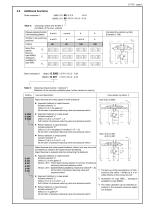
Additional functions Order examples 1: Clamping module with throttle 1) (Limitation of the max. velocity) Pressure reducing function in the switching position Throttle in the switching positions Complete flow pattern symbol (Example G 166) Spool flow pattern (here for type NSMD, analogous available for type SMD Clamping module section - tailstock 1) (Selection of the currently available types, further variants on inquiry) Flow pattern symbols 2) Use and description Rapid traverse and creep speed in both directions ' Approach tailstock in rapid traverse Actuate solenoid "a" Orifice # 2.5 in the...
Open the catalog to page 5All HAWE Hydraulik SE catalogs and technical brochures
 Pressure switch type DG 2025
21 Pages
 VR
VR15 Pages
 BVE
BVE54 Pages
 SLC
SLC17 Pages
 BNG
BNG25 Pages
 BA
BA45 Pages
 VB
VB88 Pages
 VP
VP35 Pages
 VH
VH6 Pages
 SL1
SL115 Pages
 ROLV
ROLV23 Pages
 EM
EM41 Pages
 PS
PS20 Pages
 K60N
K60N19 Pages
 V30D
V30D60 Pages
 V80M
V80M30 Pages
 V30E
V30E51 Pages
 RZ
RZ12 Pages
 Radial piston pump type R, RG
23 Pages
 C40V
C40V47 Pages
 Mini hydraulic power pack type A
23 Pages
 HR 080
17 Pages
 HICON
HICON14 Pages
 INKA
INKA35 Pages
 FXU
FXU35 Pages
 V60N
V60N71 Pages
 Product catalogue
299 Pages


