SLC
1 /17Pages

SLC
1 /17Pages
Catalog excerpts

Valve bank (directional seated valve) type SLC Product documentation Operating pressure pmax: Flow rate Qmax:
Open the catalog to page 1
© by HAWE Hydraulik SE. The reproduction and distribution of this document as well as the use and communication of its contents to others without explicit authorization is prohibited. Offenders will be held liable for the payment of damages. All rights reserved in the event of patent or utility model applications. Brand names, product names and trademarks are not specifically indicated. In particular with regard to registered and protected names and trademarks, usage is subject to legal provisions. HAWE Hydraulik respects these legal provisions in all cases. HAWE Hydraulik cannot provide individual...
Open the catalog to page 2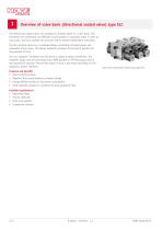
Overview of valve bank (directional seated valve) type SLC The directional seated valves are available as chained valves in a valve bank. This facilitates the combination of different circuit symbols or actuation types in order to save space, and such systems can also be used to actuate independent consumers. The SLC chained valves are a combined design consisting of seated valves and releasable check valves. This allows hydraulic actuators to be held in position for long periods of time. You can integrate T-throttles into the block to adjust actuator movements. The magnetic plugs used are connectors...
Open the catalog to page 4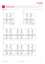
Available versions
Open the catalog to page 5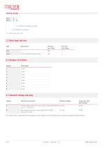
E 2.3 "Solenoid voltage and plug" 2.2 "Number of sections" 2.1 "Basic type and size" 2.1 Basic type and size Type Flow rate Qmax (lpm) with integrated throttle screws 2.2 Number of sections Coding 2.3 Solenoid voltage and plug Coding Electrical connection Nominal voltage Micro Quadlok system for 2-pin socket housing AMP 968704 12 V DC (or TE 1-1718333-1) Flat-contact housing for 2-pin plug FEP 42121600 (VW 1J0 973 702) The specifications regarding the IP protection class apply for versions featuring a properly assembled male connector.
Open the catalog to page 6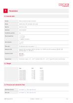
3.1 General data Version Series connection for pipe connection Seated valves with releasable check valves Aluminium, steel Installation position P = Pump T = Tank An, Bn = Consumers Flow direction Pilot ratio for releasable check valve approx. 7 : 1 Hydraulic uid Hydraulic uid, according to DIN 51 524 Parts 1 to 3; ISO VG 10 to 68 according to DIN ISO 3448 Viscosity range: 15 - 500 mm2/s Cleanliness level Environment: approx. -10 ... +50 °C, hydraulic uid: +10 ... +40 °C, ensure the correct viscosity range. 1-way chained: 2-way chained: 3-way chained: 4-way chained: 5-way chained: 6-way chained:...
Open the catalog to page 7
3.4 Electrical data Electromagnetic actuation of each single valve Coding Nominal voltage Switching voltage Relative duty cycle depending on environment, up to 50% duty cycle depending on environment, up to 50% duty cycle
Open the catalog to page 8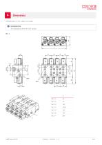
All dimensions in mm, subject to change. INFORMATION The illustrations show the 24 V version SLC 1
Open the catalog to page 9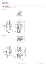
INFORMATION The illustrations show the 24 V version SLC 11-1
Open the catalog to page 10
Adjusting screw for return throttle (T-throttle)
Open the catalog to page 12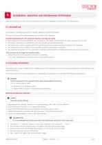
Installation, operation and maintenance information Observe the document B 5488 “General operating instructions for assembly, commissioning, and maintenance.” 5.1 Intended use This product is intended exclusively for hydraulic applications (uid technology). The user must observe the safety measures and warnings in this document. Essential requirements for the product to function correctly and safely: All information in this documentation must be observed. This applies in particular to all safety measures and warnings. The product must only be assembled and put into operation by specialist personnel....
Open the catalog to page 13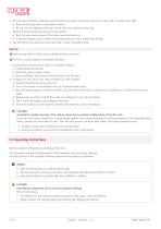
6. Turn the return throttle’s adjusting screws all the way inwards, clockwise, using the hex key with 2.5 width across ats. Note the end stop when turning them inwards. Do not turn the adjusting screw out further than ush with the valve body. 7. Apply the desired operating pressure to the product . Note the operating pressure of the higher-level machine/unit. If external leakage occurs, reduce the operating pressure and re-tighten the ttings. 8. Test the ttings and electrical connection after a week of operating time. Start-up Start-up may only be carried out by trained specialist personnel....
Open the catalog to page 14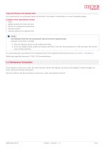
Purity and ltering of the hydraulic uid Fine contamination can significantly impair the function of the product. Contamination can cause irreparable damage. Examples of ne contamination include: ■ Swarf ■ Rubber particles from hoses and seals ■ Dirt due to assembly and maintenance ■ Mechanical debris ■ Chemical ageing of the hydraulic uid NOTICE New hydraulic uid from the manufacturer may not have the required purity. Damage to the product is possible. Filter new hydraulic uid to a high quality when lling. Do not mix hydraulic uids. Always use hydraulic uid that is from the same manufacturer,...
Open the catalog to page 15
Other information 6.1 Accessories, spare and individual parts To purchase spare parts, please see HAWE Hydraulik interactive contact map. Appropriate connector Rated voltage Micro Quadlock E system socket housing, 2-pin for coding magnetic plug
Open the catalog to page 16
Additional versions ■ valve bank (directional seated valve) type TLC 3: D 6020 TLC 3 ■ seated valve type SP 1 chained together as type SL 1: D 6024 HAWE Micro Fluid GmbH Borsigstraße 11 | 93092 Barbing | Germany Phone +49 89 379100-6000 | [email protected] | www.hawe.com hawe.com/cont
Open the catalog to page 17All HAWE Hydraulik SE catalogs and technical brochures
 Pressure switch type DG 2025
21 Pages
 VR
VR15 Pages
 BVE
BVE54 Pages
 BNG
BNG25 Pages
 BA
BA45 Pages
 VB
VB88 Pages
 VP
VP35 Pages
 VH
VH6 Pages
 SL1
SL115 Pages
 ROLV
ROLV23 Pages
 EM
EM41 Pages
 PS
PS20 Pages
 K60N
K60N19 Pages
 V30D
V30D60 Pages
 V80M
V80M30 Pages
 V30E
V30E51 Pages
 RZ
RZ12 Pages
 Radial piston pump type R, RG
23 Pages
 C40V
C40V47 Pages
 Mini hydraulic power pack type A
23 Pages
 HR 080
17 Pages
 HICON
HICON14 Pages
 INKA
INKA35 Pages
 FXU
FXU35 Pages
 V60N
V60N71 Pages
 Product catalogue
299 Pages


