SL1
1 /15Pages

SL1
1 /15Pages
Catalog excerpts

Valve bank (directional seated valve) type SL1 Product documentation Operating pressure pmax: Flow rate Qmax:
Open the catalog to page 1
© by HAWE Hydraulik SE. The reproduction and distribution of this document, as well as the use and communication of its contents to others without explicit authorization, is prohibited. Offenders will be held liable for the payment of damages. All rights reserved in the event of patent or utility model applications. Brand names, product names and trademarks are not specifically indicated. In particular with regard to registered and protected names and trademarks, usage is subject to legal provisions. HAWE Hydraulik respects these legal provisions in all cases. HAWE Hydraulik cannot provide individual...
Open the catalog to page 2
Overview of valve bank (directional seated valve) type SL1 The valve bank type SL comprises several directional seated valves type SP1 that are connected in parallel. The directional seated valves are soft-sealing valves that are technically tight in a closed condition. They are screwed into the chaining block. These blocks are clamped between the initial block (P and T port) via tension rods. In the last block, the through holes are sealed with sealing plugs. 2/2-way directly controlled directional seated valves are available. Installation position can be chosen freely. The valves feature AMP...
Open the catalog to page 4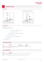
Available versions Valve bank with throttle in P and T E 2.5 "Solenoid voltage and connector" 2.4 "Throttle valve" right 2.3 "Number of sections" right of connection block 2.4 "Throttle valve" left 2.3 "Number of sections" left of connection block 2.2 "Connection block" 2.1 "Basic type and size" 2.1 Basic type and size Type Flow rate QA/B max (l/min) with directional seated valves type SP 1 2.2 Connection block Coding inlet plate Adapter plate for hydraulic power pack A100 with motor F2E, A4B or R2E
Open the catalog to page 5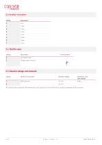
2.3 Number of sections Coding 2.4 Throttle valve Coding Circuit symbol 2.5 Solenoid voltage and connector Coding Electrical connection Nominal voltage The specifications regarding the IP protection class apply for versions featuring a properly assembled male connector.
Open the catalog to page 6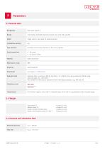
3.1 General data Designation Valve bank type SL 1 2/2 directly controlled directional seated valve with soft seal (KS) Single valve or valve bank for pipe connection Installation position Flow direction according to the arrow directions in the circuit symbols P = pump T = tank or reux Steel, aluminium Hydraulic uid Hydraulic uid, according to DIN 51 524 Parts 1 to 3; ISO VG 10 to 68 according to DIN ISO 3448 Viscosity range: 10 – 320 mm2/s Not suitable for HETG such as rapeseed oil and water-glycol solutions, e.g. HFA and HFC. Cleanliness level Environment: approx. -30 to +80 °C, hydraulic...
Open the catalog to page 7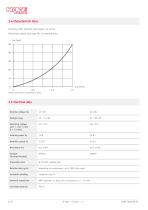
3.4 Characteristic lines Viscosity of the hydraulic uid approx. 32 mm2/s Directional seated valve type SP1 in switched state Q ow rate (l/min); Sp pressure (bar) 3.5 Electrical data Nominal voltage UN Voltage range Switching voltage (at T < +40 °C and Q < 1 l/min) Varistor (in plug housing) Protection class IP 65 with suitable plug Relative duty cycle depending on environment, up to 100% duty cycle Excitation winding Solenoid connection AMP Superseal 1,5 plug, line cross section 0,3 - 1,5 mm² Coil body material
Open the catalog to page 8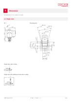
All dimensions in mm, subject to change. Mounting hole Single valve, basic version Single valve with additional check valve in outlet
Open the catalog to page 9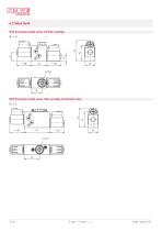
4.2 Valve bank With directional seated valves and lter cartridge SL 1..0 With directional seated valves, lter cartridge and throttle valves SL 1..2
Open the catalog to page 10
4.3 Connection block For mounting on hydraulic power pack A100 SL 1-B.. Mounting possible in both directions Hole pattern of hydraulic power pack A100 For pipe connection SL 1-A.. Mounting only possible in one direction
Open the catalog to page 11
Installation, operation and maintenance information Observe the document B 5488 “General operating instructions for assembly, commissioning, and maintenance.” 5.1 Intended use This product is intended exclusively for hydraulic applications (uid technology). The user must observe the safety measures and warnings in this document. Essential requirements for the product to function correctly and safely: All information in this documentation must be observed. This applies in particular to all safety measures and warnings. The product must only be assembled and put into operation by specialist personnel....
Open the catalog to page 12
Purity and ltering of the hydraulic uid Fine contamination can significantly impair the function of the product. Contamination can cause irreparable damage. Examples of ne contamination include: ■ Swarf ■ Rubber particles from hoses and seals ■ Dirt due to assembly and maintenance ■ Mechanical debris ■ Chemical ageing of the hydraulic uid NOTICE New hydraulic uid from the manufacturer may not have the required purity. Damage to the product is possible. Filter new hydraulic uid to a high quality when lling. Do not mix hydraulic uids. Always use hydraulic uid that is from the same manufacturer,...
Open the catalog to page 13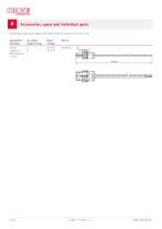
Accessories, spare and individual parts To purchase spare parts, please see HAWE Hydraulik interactive contact map. Appropriate connector for coding magnetic plug Rated voltage Female connector AMP Superseal 1.5 mm
Open the catalog to page 14
References Additional versions ■ Valve bank (directional seated valve) type SLC: D 6033-1 ■ valve bank (directional seated valve) type TLC 3: D 6020 TLC 3 For mounting on ■ Mini hydraulic power pack type A: D 6025 HAWE Micro Fluid GmbH Borsigstraße 11 | 93092 Barbing | Germany Phone +49 89 379100-6000 | [email protected] | www.hawe.com hawe.com/co
Open the catalog to page 15All HAWE Hydraulik SE catalogs and technical brochures
 Pressure switch type DG 2025
21 Pages
 VR
VR15 Pages
 BVE
BVE54 Pages
 SLC
SLC17 Pages
 BNG
BNG25 Pages
 BA
BA45 Pages
 VB
VB88 Pages
 VP
VP35 Pages
 VH
VH6 Pages
 ROLV
ROLV23 Pages
 EM
EM41 Pages
 PS
PS20 Pages
 K60N
K60N19 Pages
 V30D
V30D60 Pages
 V80M
V80M30 Pages
 V30E
V30E51 Pages
 RZ
RZ12 Pages
 Radial piston pump type R, RG
23 Pages
 C40V
C40V47 Pages
 Mini hydraulic power pack type A
23 Pages
 HR 080
17 Pages
 HICON
HICON14 Pages
 INKA
INKA35 Pages
 FXU
FXU35 Pages
 V60N
V60N71 Pages
 Product catalogue
299 Pages


